A
A
C
C
B
B
3
4
5
A
C
B
-2-
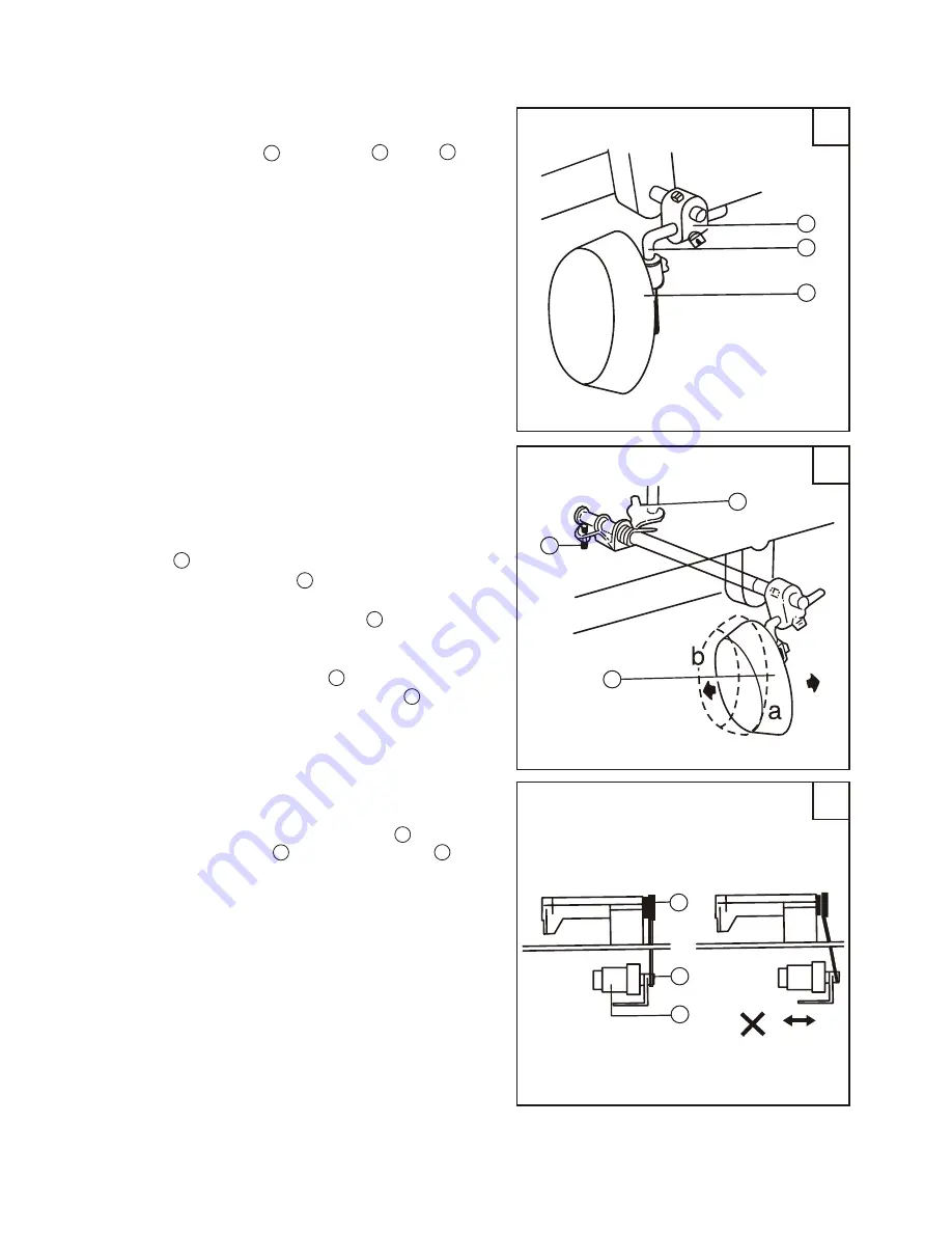
3.1.4 Knee control presser foot lifter installation(Fig.3)
a. Installing
Install Connector A , Bell Crank B , Bell C
in the order shown in Fig.3.
b. Adjustment (Fig.4)
In the order of the following:
1.When the presser foot is at its lowest posi-
tion, keep the crank in the position shown by b
in the figure, turn Knee Control Stop Adjusting
Screw C to touch with the oil reservoir, and
tighten the nut of Screw C .
2. When operate by knee, the presser foot lift
volume is controlled by Screw B . Turn the
presser foot lever down, make the bell in the po-
sition shown by a in the figure, lift the presser
foot to 13 mm, adjust Screw B to touch the oil
reservoir. Then tighten the nut of Screw B .
3.1.5 Installing the motor (Fig.5)
Align machine balance wheel belt groove A with
motor pulley belt groove B by moving the motor C
leftward or rightward. Be sure the belt is not touch
with table.
( )
( )
(
)
(
)
(
)
( )
( )
( )
( )
( )
( )


