BA 90M-P140M-P160M(D) 0802/dfe
21
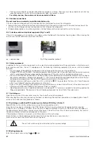
Place the unit on a level surface and engage the wheel brakes.
Ensure that the unit is complete and undamaged.
Do not tilt the unit; thermal fluid remaining in the unit from the test run could escape, soaking the insulation.
The unit may be pressurised. Danger of injury from escaping hot water or vapour.
Therefore:
– Never operate the unit without its side panels or housing.
–
Do not operate the unit in areas subject to explosion.
–
Protect the unit from sprays and cleansers containing solvents.
–
Observe all local regulations when installing the unit
.
– Repair any leaks in the temperature control circuit (unit, connecting hoses, consumer, etc.)
immediately.
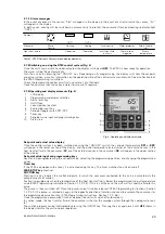
– Before disconnecting hoses in the temperature control circuit, first cool the unit by pressing
the ON/OFF switch, as required by the outlet temperature. The pump will continue to run.
The unit will cool until the heat transfer fluid has reached the programmed run-out tempera-
ture (factory setting 80 °C), and then shut off.
Ensure that the pump has stopped running and that the system pressure gauge indicates
0 bar. The display will indicate OFF.
•
In equipment in which a malfunction of the temperature control system can be hazardous to operating per-
sonnel or lead to destruction of the equipment, independent monitoring equipment must be used to moni-
tor the process and switch the equipment off safely
.
• These Operating Instructions are intended for set-up and operating personnel and must be accessible to
them at all times.
• Please ensure that these Operating Instructions are read. You will thereby save yourself unnecessary costs
and problems during set-up as well as prevent downtime.
2.2 Consumer
checks
The following checks shall be performed on the consumer prior to connecting hoses between the consumer and the
temperature control unit:
1 Check conduits for blockage.
2 Remove fluid and dirt residue using compressed air. Foreign bodies such as splinters can damage the pump.
3 Remove rust and scaling, as these strongly restrict heat transfer between the consumer and the heat transfer fluid
and increase the pressure drop in the consumer. Regloplas’ descaling agent, REG, can be used to descale (
→
”Tem-
perature Control Technology” brochure, “REG” data sheet).
Oil residue can be removed using Regloplas’ system cleanser, SR80 (
→
“Temperature Control Technology” brochure,
“SR80” data sheet).
2.3 Water
quality
To prevent damage to the temperature control unit cooler and the consumer connected to the unit, the water used
must meet the following requirements:
–
Appearance: Clear/Transparent
–
Turbidity: <0.5 NTU (light turbidity)
–
Odour: Neutral
–
Total hardness: 4–18 °d
–
ph value: 7–9
–
Conductance: max. 1000 µS/cm
The addition of the RK 93 corrosion inhibitor is strongly recommended (
→
”Temperature Control Technology” bro-
chure, “RK 93” data sheet).
2.4
Connection hoses
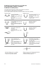
See also “Guidelines for Connecting Hoses”.
Use only pressure and temperature-resistant hoses and fittings. Do not reduce the cross-section.
–
Outlet and inlet:
If the unit is to be connected to a welded pipe system, a filter must be mounted in the inlet of
the unit due to possible residues (e.g. welding beads, forging scales).
–
The connection hoses shall be laid out to prevent accidental contact.
–
When connecting tubes, ensure that thermal expansion has been taken into account.
–
Cooling water inlet:
For connection to public mains, follow all applicable guidelines and safety regulations (e.g.
connecting the unit via a system separator).
–
The water mains pressure must lie between 2–6 bar, and be at least 0.5 bar higher than that of the system over-
pressure. (Example: Outlet temperature 140 °C, giving a system pressure of 2.6 bar + 0.5 bar = 3.1 bar minimum
required water mains pressure). This ensures trouble-free automatic refill. This condition does not apply to units
with filling pumps.

