Regency U1500E-LP11 Manual Download Page 6

6    |  U1500E-11 Gas Fireplace
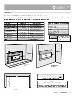
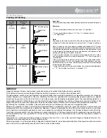
Framing & Finishing

U1500E-11 Gas Fireplace

Note: When constructing the framed opening, please 

ensure there is access to install the gas lines when 
the unit is installed. 

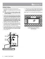
2.  For exterior walls, insulate the enclosure to the same degree as 

the rest of the house, apply vapour barrier and drywall, as per local 
installation codes. 

(Do not insulate the fireplace itself and/or the 

venting. Clearances must be maintained as per this manual.)


WARNING: Failure to insulate and add vapor barriers to the 
inside of the exterior wall will result in operational and per-
formance problems including, but not limited to: excessive 
condensation on glass doors, poor flame package, carbon, 
blue flames etc. These are not product related issues.

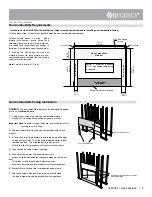
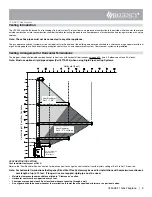
3.  The unit does not have to be completely enclosed in a chase. You 

must maintain clearances from the vent to combustible materials: 
See  "Clearances"  section.    Combustible  materials  can  be  laid 
against the side and back standoffs and the stove base.

4.  Non-combustible material (ie. tile, slate, etc) may be brought up to 

and overlap the unit (top and bottom) ensuring that the maximum 
thickness does not go beyond the 1-1/2" as shown in the diagram 
below. The faceplate will not be able to be mounted if finished 
material is beyond 1-1/2".

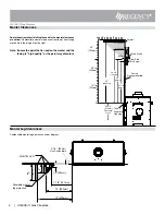
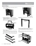
1.  Frame in the enclosure for the unit with framing material. 


IMPORTANT: The framed opening must be of non-combustible 

      material.

5.  If material such as brick, stone, etc extends past the faceplate depth 

1-1/2", when finishing around the faceplate, the minimum opening 
dimensions noted below must be adhered to ensuring for the removal 
of the faceplate and for the safe operation of this appliance.

NOTE: Spacing of 1"around the completed surround must be adhered to.

Unit shown with inner door frame only

Using the clean edge of the unit shown in 

a typical tiled facing. 

49-7/8"

18-1/16"

Ensure  front  of  facing  material  is  flush  with 
the edge of the flange on the fireplace. 

Summary of Contents for U1500E-LP11

Page 1: ...er 5 Inner 8 Outer CSA P 4 1 67 46 69 64 Approved Venting Systems Flex Vent Systems FPI AstroCap Flex Vent Rigid Pipe Vent Systems Simpson Direct Vent Pro Selkirk Direct Temp American Metal Products Metal Fab Sure Seal Security Secure vent ICC Excel 45 1 4 49 11 16 13 1 2 29 1 16 24 1 4 6 3 16 32 5 8 12 1 4 23 15 16 22 1 16 54 5 16 1381mm 49 11 16 1263mm 312mm 512mm 609mm 1263mm 1150mm 674mm 737mm...

Page 2: ... 16 43mm J Gas Connection Height 2 11 16 67mm K Gas Connection Inset 1 1 8 29mm L Gas Connection Opening Width 4 11 16 119mm Framing depth measurement is noted with the nailing strips set as far forward on the firebox as possible The nailing strips can be adjusted back up to 1 1 2 38mm to allow for varying thicknesses in non combustible material wall finishes See non combustible section in the ins...

Page 3: ...t this fireplace and vent system be installed only in accordance with these instructions Installed close to ceiling Flue Pipe Clearances to Combustibles Horizontal Top 3 Horizontal Side 2 Horizontal Bottom 2 Vertical 2 Passing through wall floor ceiling when firestop is used 1 1 2 Alcove E F F E D A B Installed Close to Floor G The HeatWave Duct Kit has different clearance and fram ing requirement...

Page 4: ...nd the facing is high quality or the paint may discolour Mantel Leg Clearances Combustible mantel leg clearances as per diagram Wood Studs 0 Non combustible Facing 34 864mm 24 1 4 616mm 10 254mm 30 762mm Top of Fireplace Opening 20 508mm 6 152mm 12 305mm 29 1 2 749mm Steel Stud On Edge 1 25mm 23 7 8 606mm 6 152mm 12 305mm Drywall From base of unit 25 635mm 4 Allowable mantel leg projection 7 1 8 1...

Page 5: ... cracked seams 4 Tape the seams using a mesh type tape 5 Mud seams as normal We recommend using a product called Durabond high strength compound for the first coat This product can be found most hardware stores Mud must be cured as per manufacturer s recommendations 6 Prime wall for a second time for proper adhesion of paint 7 Paint walls using a high quality paint which will withstand the high te...

Page 6: ...ustible materials See Clearances section Combustible materials can be laid against the side and back standoffs and the stove base 4 Non combustible material ie tile slate etc may be brought up to and overlap the unit top and bottom ensuring that the maximum thickness does not go beyond the 1 1 2 as shown in the diagram below The faceplate will not be able to be mounted if finished material is beyo...

Page 7: ...o exception to this rule Therefore the units are specified with non combustible required materials to specific dimensions above and around the units This is due to these areas reaching higher temperature levels than required acceptable for a combustible material To obtain the best most durable finish around your fireplace this calls for a high level of care and attention to the preparation and fin...

Page 8: ... 2 screws on each nailing strip adjust and retighten screws 4 Attach both vertical studs 676 036 A to the vertical timber studs and secure using 6 screws 2 at bottom 2 at top and 2 on sides as shown NOTE Ensure the flat side of the steel stud is facing the wood framing 676 036 A Flat side out 5 Secure horizontal steel header stud 606 067 with 2 screws per side as per diagram 6 Slide the unit into ...

Page 9: ...ing one 90o two 45o elbows equal one 90o elbow Note Must use optional rigid pipe adapter Part 770 994 when using Rigid Pipe Venting Systems Maintain clearances to combustibles as listed in Clearances section Horizontal vent must be supported every 3 feet Firestops are required at each floor level and whenever passing through a wall A vent guard should be used whenever the termination is lower than...

Page 10: ...o elbows equal to one 90o elbow Vent must be supported at offsets Minimum distance between elbows is 1 ft 305mm Maintain clearances to combustibles as listed in the Clearances section Horizontal vent must be supported every 3 feet Firestops are required at each floor level and whenever passing through a wall Must use optional rigid pipe adaptor Part 510 994 when using rigid pipe vent systems Refer...

Page 11: ... with Two 2 90o Elbows One 90o elbow Two 45o elbows Option V H H1 With these options maxi mumtotalpipelengthis30 feetwith minimum of 6feet totalverticalandmaximum 8 feet total horizontal Please note minimum 1 foot between 90o elbows is required A 1 Min 3 Max B 2 Min 4 Max C 3 Min 5 Max D 4 Min 6 Max E 5 Min 7 Max F 6 Min 8 Max Restrictor Set 0 5 Factory Setting Option V H V V1 H H1 With these opti...

Reviews: