


U1500E-11 Gas Fireplace | 5
U1500E-11 Gas Fireplace
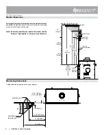
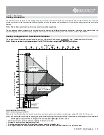
48
-3
/1
6"
(1
22
4m
m
)
3-1/4"
(83mm)
23-7/8" (606mm)
56-1/2"
(1435mm)
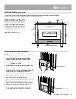
Non-combustible
Material
Non-combustible
Non-combustible
Steel Stud Header
on edge
Wood Stud
Wood Stud
24-5/16" (6171mm)
Combustible
Material
3-1/4"
(83mm)
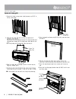
Non-Combustible Facing Installation
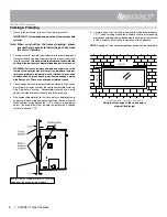
Non-combustible board
Non-combustible board-faces and edges
MUST BE PRIMED.
Non-combustible board
Caution:
The non-combustible board can be damaged if dropped
or struck.
Handle with care.
1. Using drywall screws - secure non combustible material
around unit, framing and top nailing strip every 6 inches.
Important Note: To avoid cracking the board - pre-drill holes prior to
securing to unit/ framing.
2. Wipe any debris/dust from the non combustible material and
drywall.
3. Prior to securing it is mandatory to prime the facing and edges
using a quality primer. This will ensure proper adhesion of both
the tape and mud. The supplied board is very porous.
Failure to follow this procedure will result in cracked seams.
4. Tape the seams using a mesh type tape.
5. Mud seams as normal. We recommend using a
product called Durabond high strength compound - for the first
coat.
This product can be found most hardware stores.
Mud must be cured as per manufacturer’s recommendations.
6. Prime wall for a second time for proper adhesion of paint
7. Paint walls using a high quality paint which will withstand
the high temperatures being emitted from this appliance.
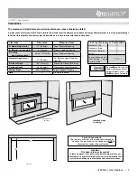
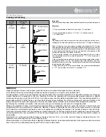
Non-Combustible Requirements
* Installation of the ON/OFF Wall Switch/Battery Holder must be completed before installing non-combustible facing.
All three pieces (top, 2 sides) are supplied to meet the non combustible requirements.
Calcium silicate board is a high - grade
material with cement, quartz, natural and
selected minerals as the main raw materials.
It is widely used for partitions and ceilings in
buildings. It is fire proof and earthquake proof.
If finishing the wall above the unit with
materials such as tile, brick, marble, etc. non-
combustible board available from the building
supply store can be used.
Note: Calcium Silicate is 1/2' thick
NOTE: A minimum thickness
of 1/2" non combustible facing
is required.
Drywall or similar materials


