


U1500E-11 Gas Fireplace | 3
U1500E-11 Gas Fireplace
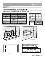
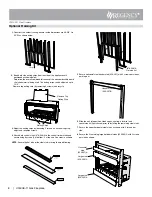
Caution Requirements
The top, back and sides of the fireplace are defined by
standoffs. The metal ends of the standoff may
NOT be
recessed into combustible construction.
WARNING
Fire hazard is an extreme risk
if these clearances (air space) to combustible materials are not
adhered to. It is of greatest importance that this fireplace and vent
system be installed only in accordance with these instructions.
Clearances
The clearances listed below are minimum distances unless otherwise stated.
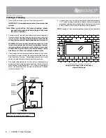
A major cause of chimney related fires is failure to maintain required clearances (air space) to combustible materials. It is of the greatest impor-
tance that this fireplace and vent system be installed only in accordance with these instructions.
Installed close
to ceiling.
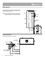
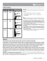
Flue Pipe Clearances to Combustibles
Horizontal - Top
3"
Horizontal - Side
2"
Horizontal - Bottom
2"
Vertical
2"
Passing through wall/
floor/ceiling - when
firestop is used.
1-1/2"
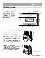
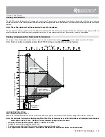
Alcove
E
F
F
E
D
A
B
Installed Close
to Floor
G
The
HeatWave
Duct Kit has
different clearance and fram-
ing requirements, check the
HeatWave
manual for details.
Clearance:
Dimension
Measured From:
A: Mantel Height (min.)
25" (635mm)
Top of Fireplace Opening
B: Sidewall (on one side)
6" (152mm)
Side of Fireplace Opening
C: Ceiling
(room and/or alcove)
46-1/4" (1175mm)
Top of Fireplace Opening
D: Mantel Depth (max.)
12" (305mm)
34" (864mm) Above Fireplace
Opening
E: Alcove Width
60" (1524mm)
Sidewall to Sidewall (Minimum)
F: Alcove Depth
36" (914mm)
Front to Back Wall (Maximum)
G: From Floor
24-1/4" (616mm)
Top of Fireplace Opening
Note:
0"
No hearth required


