10
FG39-2 Freestanding Gas Stove
installation
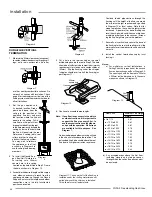
FLUEING ARRANGEMENTS
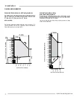
Vertical Terminations Using
Dura-Flue Flueing System
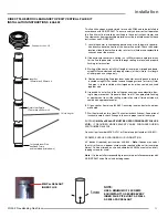
The shaded area in the diagram below shows all allowable combi-
nations of straight vertical and offset to vertical runs with vertical
terminations.
Maximum two 45
o
elbows
.
If the flue is ENCLOSED in a chase 229mm x 229mm maintain a 32mm
clearance to combustibles.
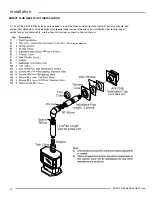
Horizontal Terminations for All Flueing Systems
The shaded areas in the diagram below show all allowable combina-
tions of vertical runs with horizontal terminations. Maximum one
90
O
elbow (two 45
o
elbows equal one 90
o
elbow).
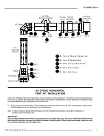
LPG and NG:
The flueing arrangements diagrammed below, have a minimum of 75%
(flue loss) efficiency with Fan Off, as required for manufactured homes.
(Actual efficiency may be as high as 85%)
Horizontal Run (Metres)
1.5m Min.
1.8m
1.5m
0.9m
Min.
0.3m
3.7m Max.
4.0m
1
1
Vertical Height (metres)
6.2m Max.
0.6m
1.2m
1.8m
3m
2.4m
3.7m
4.3m
0.6m
4.9m
1.2m
3m
2.4m
6.1m
6.7m
7.3m
1.8m
4.3m
5.5m
7.3m Max.
3.2m Max.
1
o
1
45
1.8m Max.
0.6m
3.7m
1.8m
4.9m
1.2m
4.3m
5.5m
3m
Horizontal Distance (Metres)
Vertical Height (Metres)
Maximum 9.1m
0.6m
1.2m
1.8m
2.4m
2.4m
6.1m
6.7m
7.3m
7.9m
7.9m
9.1m


