


Regency U31-10 Gas Fireplace Insert
|
19
|
19
installation
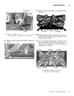
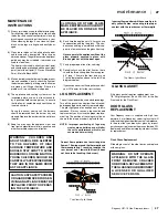
Diagram 4
Diagram 5
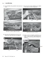
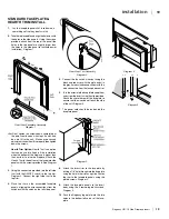
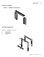
Rear View: Trim Assembly
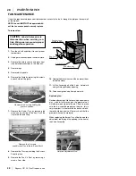
Diagram 2
Diagram 3
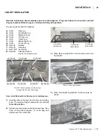
Rear View: Faceplate Assembly
Diagram 1
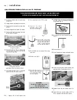
STANDARD FACEPLATE &
HEARTH TRIM INSTALL
1.
Lay the faceplate panels flat, face down on
something soft so they don't scratch.
2.
Take the top faceplate and align the holes in it with
the holes in the side panels. Using the screws
provided, attach from the top of the panel (the
holes in the top panel are slightly larger than
the holes in the side panel to facilitate easier
installation). Diagram 1.
Hint: Don't tighten the screws down completely at
this point, continue on with steps 3 and 4 and
do a trial fit to the unit. Make any necessary
adjustments and when it fits properly then tighten
down the screws.
Hearth Trim Option:
Hearth Trim is an option
that can be used to finish off the installation
when the bottom of the fireplace is higher than
the hearth or to raise the fireplace. Attach the
Hearth Trim to the bottom of the faceplate side
panels with the screws provided. See Diagram
1.
3.
Using the connectors provided, join the left side
trim (with the ON/OFF switch) to the top trim.
Diagram 2. Connect the right side trim to the
top trim.
4.
Place the trim on the assembled faceplate
panels, aligning the wire connections from the
switches with the notch on the left side panel.
5.
Connect the fan switch wires by taking the
black and red wires with the male ends (in
the grey harness) and connect them with the
wire connectors from the fan speed control.
6.
Tuck the wires into the faceplate to keep them
away from the insert using the clip provided.
Attach the clip to the rear of the faceplate to
ensure that the wires do not touch the side
of the unit. Diagram 3.
7.
The power cord should be run behind the
faceplate panel.
8.
Attach the brass trim to the faceplate by
drilling a 1/8" hole through into the faceplate
using the hole in the trim as a guide. Fasten
the trim to the faceplate panels using the
plated screws. Diagram 4.
9.
Attach the faceplate panels to the insert
body using the 4 remaining black screws.
Diagram 5.
10.
Push the Regency logo plate into the two
holes in the bottom left corner of the face-
plate.
Summary of Contents for Energy U31-LP10
Page 1: ......
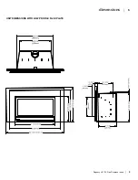
Page 5: ...4 Regency U31 10 Gas Fireplace Insert 4 dimensions UNIT DIMENSIONS WITH STANDARD FACE PLATE ...
Page 33: ...32 Regency U31 10 Gas Fireplace Insert 32 notes ...
Page 34: ...Regency U31 10 Gas Fireplace Insert 33 33 notes ...
Page 35: ...34 Regency U31 10 Gas Fireplace Insert 34 notes ...


