


Regency U31-10 Gas Fireplace Insert
|
9
|
9
installation
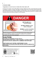
IMPORTANT:
SAVE THESE INSTRUCTIONS
The Regency Gas Insert must be installed in
accordance with these instructions. Carefully
read all the instructions in this manual first.
Consult the building authority having jurisdic-
tion to determine the need for a permit prior to
starting the installation.
NOTE: Failure to follow the instructions
could cause a malfunction of the
heater which could result in death,
serious bodily injury, and/or prop
-
erty damage. Failure to follow these
instructions may also void your fire
insurance and/or warranty. This appli
-
ance can be used with a thermostat.
FOR YOUR SAFETY
This appliance requires air for proper combus-
tion. Always provide adequate combustion
and ventilation air. Follow instructions and
information in CAN/CGA B149 (in Canada) or
the National Fuel Gas Code ANSI Z223.1 (in the
USA), regarding requirements for combustion
and ventilation air.
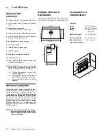
SPECIFICATIONS
At pressures over 1/2 psig, the pipe to the unit
must be disconnected.
Gas Input Capacity:
Natural Gas
30,000 Btu/h
Propane
28,000 Btu/h
Fuels:
Approved for use with both natural gas,
and propane. Approved as is for use at 0' to 2,000'.
With a field installed conversion kit 0' - 4,500'.
Electrical:
120V A.C. system.
Circulation Fan:
Variable speed, 127 CFM.
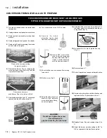
Log Set:
Ceramic fibre, 7 per set.
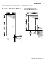
Vent System:
Minimum 4" B-Vent or listed
gas fuel vent liner.
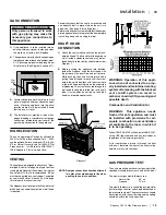
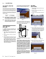
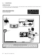
GAS PRESSURE TESTING
The appliance must be isolated from the gas
supply piping system by closing its individual
manual shut off valve during any pressure
testing of the gas supply piping system at test
pressures equal to or less than 1/2 psig. (3.45
kPa). Disconnect piping from valve at test pres-
sures over 1/2 psig (3.45 kPa).
POLICY FOR SOLID FUEL
BURNING AND FACTORY
BUILT FIREPLACES
The FPI U31-10 may be installed and vented into
any solid fuel fireplace that has been installed
in accordance with the National, Provincial and
local building codes and is constructed of non-
combustible materials.
1.
Installer must mechanically attach the supplied
label to the inside of the firebox of the fireplace
into which the gas fireplace insert is installed.
WARNING:
This fireplace has been con-
verted for use with a gas fireplace insert
only and cannot be used for burning wood or
solid fuels unless all original parts have been
replaced, and the fireplace re-approved by
the authority having jurisdiction.
2.
Do not cut any sheet-metal parts of the fireplace,
in which the gas fireplace insert is to be installed.
3.
If the factory-built fireplace has no gas access
hole(s) provided, an access hole of 1-1/2"
(37.5mm) or less may be drilled though the
lower sides or bottom of the firebox in a proper
workmanship like manner. This access hole
must be plugged with a non-combustible insula-
tion after the gas supply line has been installed.
4.
The fireplace flue damper can be fully blocked
open or removed for installation of the gas
fireplace insert.
5.
The fireplace and fireplace chimney must be
clean and in good working order and constructed
of non-combustible materials.
6.
The chimney cleanouts must fit properly.
7.
Refractory (firebricks), glass doors, screen rails,
screen mesh and log grates can be removed
from the fireplace before installing the gas
fireplace insert.
8.
Smoke shelves, shields and baffles may be
removed if attached by mechanical fasteners.
If any part is removed it must not weaken the
structural integrity of the factory built.
9.
Trim panels or surrounds shall not seal ventila-
tion openings in the fireplace.
BEFORE YOU START
Safe installation and operation of this appliance
requires common sense, however, we are required
by the Canadian Safety Standards and ANSI Stand-
ards to make you aware of the following:
GENERAL SAFETY INFORMATION
1.
The appliance installation must conform with
local codes or in the absence of local codes,
with CAN/CGA B149 (in Canada) or the
National Fuel Gas Code ANSI Z223.1. This
appliance should be installed by a qualified
gas fitter technician only.
2. Installation and repair should be done by a
qualified service person.
3.
The appliance should be inspected before use
and at least annually by a professional service
person. More frequent cleaning may be required
due to excessive lint from carpeting, bedding
material, animal hair, etc. It is imperative that
control compartments, burners and circulating
air passageways of the appliance be kept clean.
4.
See general construction and assembly instruc-
tions. This appliance may only be installed in a
vented, noncombustible fireplace.
5.
This appliance is Listed for bedroom installa-
tions. In Canada room heaters must be installed
with a Listed Millivolt Thermostat. Some areas
may have further requirements, check local
codes before installation.
6.
This unit is not approved for installation into a
mobile home.
7.
Always connect this insert to a vent system
venting to the outside of the building envelope.
Never vent to another room or inside a building.
Make sure that the vent is properly sized and is
of adequate height to provide the proper draft.
8.
Inspect the venting system annually for blockage
and any signs of deterioration.
9.
Any glass removed for servicing must be re-
placed prior to operating the appliance.
10.
To prevent injury, do not allow anyone who is
unfamiliar with the operation to use the fireplace.
11.
Failure to position the parts in accordance with
the diagrams in this manual or failure to use only
parts specifically approved with this appliance
may result in property damage or personal injury.
12.
Due to high temperatures, the appliance should
be located out of high traffic areas and away
from furniture and draperies. Children and
adults should be alerted to the hazards of high
surface temperatures, especially the fireplace
glass and gold trims, and should stay away to
avoid burns or clothing ignition. Young children
should be carefully supervised when they are
in the same room as the appliance. Clothing or
other flammable material should not be placed
on or near the appliance.
Emissions from burning wood or gas could
contain chemicals known to the State of
California to cause cancer, birth defects or
other reproductive harm.
Summary of Contents for Energy U31-LP10
Page 1: ......
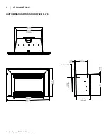
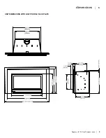
Page 5: ...4 Regency U31 10 Gas Fireplace Insert 4 dimensions UNIT DIMENSIONS WITH STANDARD FACE PLATE ...
Page 33: ...32 Regency U31 10 Gas Fireplace Insert 32 notes ...
Page 34: ...Regency U31 10 Gas Fireplace Insert 33 33 notes ...
Page 35: ...34 Regency U31 10 Gas Fireplace Insert 34 notes ...