background image

23

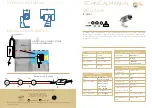
DRAWING NO. 9 — CONTROL VALVE ASSEMBLY 
Part Number 7004 - 1000/2000 PPD

Part No.      Quantity       Description                    


7100                   1              Yoke                                
7102                  1              Top Body                      
7104                  1              Bottom Body                
7106                  1              Valve Plug                 
7108                  1              Valve Seat                  
7109                  1              Lead Screw                  
7110 

*

                1              Nut Plate                     

7111                  3              Standoff                      
7112                  1              Mounting Plate            
7113                  1              Indicator Screw          
7114                  1              Indicator Nut              
7116                  1              Knob/Knurled               
7117                  1              Indicator Plate           
7118                  1              Driver Gear                 
7119                  1              Follower Gear             
7120                  1              Stepper Motor             
7121                  1              Potentiometer 
7122                   1              Guide/Retainer                        
7124                  1              S-405 “O” Ring 
7125                  1              S-415 “O” Ring 
7126                  1              S-407 “O” Ring                         
7127                  1              S-414 “O” Ring             
7128                  1              Seal                             
7129                  1              Seal 
7130                  1              Seal                                                     
7131                  4              Screw-#10-24 X 2 1/2       
7132                  1              Screw-#10-24 X 1/2     
7133                  4              Screw-#10-32 X 1        
                                          with “O” Ring            
7135                  5              #10 Lock Washer          
7136                  3              #10-32 Nut                               
7139                  1              #8-32 Nut                        
7140                  2              Screw-#6-32 X 1/4                          
7142                  2              #6-32 Set Screw X 3/8      
7143                  4              #6-32 Set Screw X 1/4      
7190                   3             Shoulder Screw                           
7191                   1             Cap Screw       
7192                   1             Spring       
MS19 

*

               2             1" NPT Union           

MS21 

*

              2             1" NPT Close Nipple              


*NOTES:


1. P/N 7110 not shown. 
   1/8 x 7/16 x 2 1/4 

 
2. P/N 7123 is not part of this assembly. 

 
3. MS19 and MS21 fittings not shown. 

Summary of Contents for Smartvalve 7001

Page 1: ...nt is suitable for use only with the gases specified DO NOT USE THIS EQUIPMENT WITH OTHER GASES Such use can result in failures having hazardous consequences 2 This equipment is designed FOR VACUUM SE...

Page 2: ...against material defects in components and workmanship occurring in the course of manufacture Buyer s sole remedy for breach of said warranty shall be at C I s option either repair or replacement of...

Page 3: ...ct to open or close the valve 8 Do not reuse lead gaskets They may not seal properly thereby permitting the release of gas 9 Use only lead gaskets Other types may contract with temperature variations...

Page 4: ...ing the Analog Output C Setting the Mechanical Zero 8 0 MAINTENANCE 9 0 SPECIFICATIONS A To Enter the Configuration Mode B Configuration Parameters C To Exit the Configuration Mode 5 0 CONFIGURATION M...

Page 5: ...ly Circuit Board Part No 7071 Drawing No 7 Use of External Surge Suppressors Consult manufacturer of surge suppressor for installation and wiring specifics Drawing No 8 Control Valve Assembly for 10 t...

Page 6: ...the middle third of the system s capacity maximum feed rate 2 The water flow meter and transmitter must be sized or scaled so the maximum water flow coincides with the maximum feed rate capacity of t...

Page 7: ...ting to the vacuum fitting on the ejector assembly 5 Finally connect a length of tubing from the bottom connection of the pressure relief valve routing it outside with the end facing down and protecte...

Page 8: ...isplay screen reads ENT ENG PW 0 Enter Engineering Password 2 Press the NEXT keypad button three times until the factory default password 0 0 0 0 appears Then press ENT enter to accept 3 The TOP LINE...

Page 9: ...eatedly until the preferred FIRST digit is displayed Then press NEXT to accept the new value b The number 0 will appear as the second digit Once again use UP or DOWN to scroll to the preferred number...

Page 10: ...red and designate what condition the alarm represents The selections are OFF LOW or HIGH If the SET POINT MODE setting is left in the factory default OFF position no additional parameters will be made...

Page 11: ...ading of 0 45 V NOTE A voltage reading from 0 41 to 0 49 is acceptable IMPORTANT If for some reason the voltage reading falls outside of the acceptable range contact Chlorinators Incorporated for assi...

Page 12: ...t the feed rate simply turn the thumbwheel while using the remote meter ball float as a guide 4 Fully Manual If it is necessary to temporarily bypass the SMARTVALVE entirely use the remote meter rate...

Page 13: ...t Press ESC a second time and SAVE CHANGES to return to the main operating screen C SETTING MECHANICAL ZERO See Drawing No 8 for Model 7001 or No 9 for Model 7006 The mechanical zero valve plug positi...

Page 14: ...AM 16 Bit Display 20 character 2 line Backlit LCD Relays Three 3 each 10A 250 VAC Environmental Limits 32 to 120 F 0 to 50 C Calibration Accuracy 0 25 from zero Speed of Response Variable and field se...

Page 15: ...Union Typ BY OTHERS Gauge for Supply Pressure Ps BY OTHERS Gauge for Back Pressure Pb BY OTHERS REGAL Model CRA 5000 Residual Analyzer REGAL VAC 1000 Vacuum Monitor Static Mixer BY OTHERS Residual Sa...

Page 16: ...Ball Valve 1 PVC Ball Valve 3 PVC Ball Valve Chemical Solution Injection Point Water Flow Meter 4 20 mA Analog Flow Input Signal 4 20 Milliamp Analog Output Signal 1 For Automatic Operation open ball...

Page 17: ...valve tool supplied with your REGAL chlorinator system into the slot and tilt the screwdriver in the direction of the terminal number This will open the clamp and allow the wire to be inserted Remove...

Page 18: ...RIGHT SIDE JUNCTION BOX 1 L See Note 1 2 N See Note 1 3 Ground See Note 1 4 N O Relay K1 5 Com Relay K1 6 N C Relay K1 7 N O Relay K2 8 Com Relay K2 9 N C Relay K2 10 N O Relay K3 11 Com Relay K3 NOT...

Page 19: ...19 DRAWING NO 5 DISPLAY CIRCUIT BOARD Part Number 7070 NOTE All wiring connections to this circuit board are made at the factory prior to shipment See Drawing No 4 for Field Wiring...

Page 20: ...20 DRAWING NO 6 POWER RELAY CIRCUIT BOARD Part Number 7071 NOTE All wiring connections to this circuit board are made at the factory prior to shipment See Drawing No 4 for Field Wiring...

Page 21: ...h Grounding Rod External Surge Protection Device Typ BY OTHERS IMPORTANT Consult the manufacturer of the transient voltage surge suppression device for proper wiring of inputs and outputs Analog and d...

Page 22: ...7121 1 Potentiometer 7124 3 S 405 0 Ring 7127 1 S 414 0 Ring 7128 2 Seal 7129 1 Seal 7131 4 Screw 10 24 X 2 1 2 7132 1 Screw 10 24 X 1 2 7133 4 Screw 10 32 X 1 with O Ring 7135 5 10 Lock Washer 7136...

Page 23: ...r 7121 1 Potentiometer 7122 1 Guide Retainer 7124 1 S 405 O Ring 7125 1 S 415 O Ring 7126 1 S 407 O Ring 7127 1 S 414 O Ring 7128 1 Seal 7129 1 Seal 7130 1 Seal 7131 4 Screw 10 24 X 2 1 2 7132 1 Screw...

Page 24: ...24 DRAWING NO 10 ENGINEERING DATA SHEET Series 7000 SMARTVALVE Dimensions DIMENSIONS INCHES mm 7500 REMOTE METER PANEL SMARTVALVE...

Page 25: ...e Valve Plug O Ring 11 S 406 2 Meter Tube Plug O Ring 12 Z 815 4 Screw 1 4 20 x 1 Long 13 ZZ 278 1 Plug 1 2 NPT 14 See Chart 2 Tube Fitting Elbow Not Shown NOTE If system is using 1000 PPD or 2000 PPD...

Page 26: ...Metering Tube Float Assembly 1000 PPD 20 Kg Hr 2000 PPD 40 Kg Hr Flow Meter Inlet Block Back Panel Mounting Screws For RV 810 RV 814 Base Plate for RV 814 Rate Valve Seat Plug with 2 S 803 Seals NOTES...

Page 27: ...pad 1 At dosage settings greater than 100 proportionality is lost at some water flow rate less than the designed maximum rate If the dosage setting is increased to 200 for example proportional control...

Page 28: ...2019 Chlorinators Incorporated Printed in U S A Pub No 0919 3 1044 SE Dixie Cutoff Road Stuart Florida 34994 USA Phone 772 288 4854 Fax 772 287 3238 www regalchlorinators com Email regal regalchlorin...

Reviews: