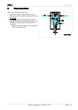
background image

Installation 


24 —  English  

Vacuum spray degassing — 06.07.2016 - Rev. B 


6.4.2


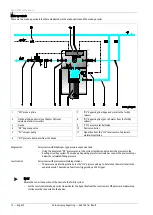
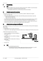
Level dependent "Levelcontrol" make-up mode 


The device is in "Levelcontrol" operating mode which is used for systems with pressure maintenance stations. 


Pressure maintaining station 


Device 

"WC" make-up line 


"DC" degassing line (degassed water) 

For optional equipment and accessories, see chapter 4.6 
"Optional equipment and accessories"
 on page 13  


"DC" degassing line (gas-rich water) 

 
The "Levelcontrol" operating mode is set in the Customer menu of the device controller. This operating mode is used for facilities with 
pressure maintaining stations and enables an elastic operation at constant pressure. 
Water is added depending on the measured filling level in the expansion tank of the pressure maintaining station. The "LIS“ pressure 
pick-up determines the filling level and sends this value to the controller of the pressure maintaining station. The controller sends a 230 
V signal to the device controller when the filling level in the expansion tank has fallen below the set value. The device controller 
regulates the motor actuator of the 3-ways motor ball valve in the "WC" make-up line. This ensures a controlled make-up with water and 
monitoring of the make-up time and cycles. 


Summary of Contents for Servitec 30

Page 1: ...Vacuum spray degassing 06 07 2016 Rev B Servitec 30 GB Operating manual Original operating manual...

Page 2: ......

Page 3: ...6 6 1 Installation conditions 17 6 1 1 Incoming inspection 17 6 2 Preparatory work 17 6 3 Execution 18 6 3 1 Fitting the add on components 19 6 3 2 Wall mounting 19 6 3 3 Hydraulic connection 20 6 4 S...

Page 4: ...e menu 38 9 4 Default settings 39 9 5 Parametrising the controller in the Customer menu 40 9 6 Messages 44 10 Maintenance 47 10 1 Maintenance schedule 48 10 2 Cleaning 49 10 2 1 Cleaning the dirt trap...

Page 5: ...installing this equipment or performing any other work at the equipment is required to carefully read this manual prior to commencing work and to comply with its instructions The manual is to be provi...

Page 6: ...on with the signal word Warning indicates imminent danger failure to observe the safety information can result in death or severe irreversible injuries CAUTION Damage to health The sign in combination...

Page 7: ...and into the make up water Note Ensure the quality of the make up water as specified by national regulations For example VDI 2035 or SIA 384 1 Note To ensure fault free operation of the system for the...

Page 8: ...installation removal or maintenance work at the connection points CAUTION Risk of injury upon coming into contact with glycol containing water Contact with glycol containing water in plant systems for...

Page 9: ...zed systems The device provides the following safety features No direct intake of air thanks to a regulation of the pressure maintenance with automatic make up No circulation issues caused by free bub...

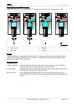
Page 10: ...em and the fresh water from the make up line It removes up to 90 percent of the dissolved gases from the water The degassing operation uses timer controlled cycles A cycle comprises the following phas...

Page 11: ...rovides 3 different degassing programmes and 2 different make up variants for selection and setting Degassing programmes Continuous degassing For continued degassing over several hours or days in a se...

Page 12: ...transducer from the device Magcontrol For systems with diaphragm type pressure expansion tank Using the integrated PIS pressure sensor the system registers and monitors the pressure in the heating or...

Page 13: ...ake up water from the public water network Fillsoft is installed between Fillset and the device The device controller evaluates the make up quantities and signals a required replacement of the softeni...

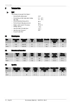
Page 14: ...54 5 1 Electrical system Type Power output kW Power supply V Hz Fusing A Number of RS 485 interfaces I O module Electrical voltage control unit V A Noise level dB 30 0 47 230 50 10 1 No 230 4 55 30 G...

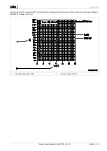
Page 15: ...06 07 2016 Rev B English 15 Approximate values for the maximal Va system volume to be degassed under extreme conditions during commissioning at a nitrogen reduction from 18 mg l to 10 mg l 1 Continuou...

Page 16: ...if pressurised hot water or hot steam suddenly escapes Ensure proper installation removal or maintenance work Ensure that the system is de pressurised before performing installation removal or mainte...

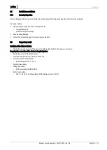
Page 17: ...3 Contact the forwarding agent to register your complaint 6 2 Preparatory work Condition of the delivered device Check all screw connections of the device for tight seating Tighten the screws as neces...

Page 18: ...dmixture or a hydraulic switching point connect the device upstream of the switching point In this manner you ensure the water degassing in the V main volume flow at temperatures 70 C CAUTION damage d...

Page 19: ...t connect the automatic make up close the WC connection with a G blind plug 2 Attach the ball valve with the ST dirt trap at the DC inlet of the degassing 3 Attach the ball valve at the DC outlet of...

Page 20: ...ng pipes as shown below Proceed as follows Prevent an overload of the ST dirt trap in the device caused by coarse dirt Install the DC gas rich degassing line upstream of the gas poor degassing line wh...

Page 21: ...e requires two DC degassing lines to the plant system One degassing line for the gas rich water from the plant system One degassing line for the degassed water back to the plant system Install the deg...

Page 22: ...connect receptacle its bottom edge must be at least 100 mm over the PU device pump Close the connection of the WC makeup line when a makeup line is not connected Adjust the Levelcontrol makeup variant...

Page 23: ...1 Pressure dependent Magcontrol make up mode 1 Diaphragm expansion tank 5 DC degassing line degassed water 2 WC make up line 6 DC degassing line gas rich water 3 For optional equipment and accessories...

Page 24: ...ce controller This operating mode is used for facilities with pressure maintaining stations and enables an elastic operation at constant pressure Water is added depending on the measured filling level...

Page 25: ...wer source and secure it against unintentional reactivation 2 Remove the cover DANGER Risk of serious injury or death due to electric shock Some parts of the device s circuit board may still carry 230...

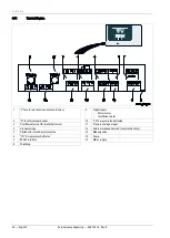
Page 26: ...er meter Insufficient water 2 N fuse for solenoid valves 10 CD 3 ways motor ball valve 3 Overflow valve not for motor ball valve 11 Pressure analogue input 4 Group message 12 External makeup demand Le...

Page 27: ...tional 17 Makeup 230 V 18 Makeup 230 V 19 PE shield Level analogue input not used by the device 20 Level signal 21 Level 18 V 22 PE shield Pressure analogue input for display and makeup controller mus...

Page 28: ...equired please contact the Reflex Customer Service for the protocol of the RS 485 interface details of the connections and information about the accessories offered 6 5 2 1 Connecting the RS 485 inter...

Page 29: ...sioned in accordance to the instructions provided in the Operating Manual The settings in the controller match the local conditions Note When any factory set values of the device are changed you must...

Page 30: ...e entire system is filled with water and all gases have been vented in order to ensure a circulation through the entire system The electrical connection has been created according to applicable nation...

Page 31: ...ways motor ball valve to the system 2 Start turning the PU vacuum pump at the fan wheel using a screw driver CAUTION Injuries caused by pump start up Hand injury due to a pump start Switch the pump t...

Page 32: ...g read the entire operating manual and verify the proper assembly Read the operating manual Only displayed if Magcontrol has been selected in the Servitec menu option P0 calculation see chapter 7 2 Se...

Page 33: ...y activated to remove any residual free or dissolved gases from the system This time can be set in the Customer menu as required by the system conditions The default setting is 24 hours Subsequent to...

Page 34: ...ual system The default setting is 24 hours After expiry of the set time the device automatically switches to interval degassing Continuous degassing Interval degassing of the system water Designed for...

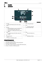
Page 35: ...Up and Down buttons Selects PU or CD OK button Starts and shuts down PU or CD Quit button Shuts down PU or CD in reverse sequence The last pressing switches you to Stop mode Auto button Return to Auto...

Page 36: ...etrising the controller in the Customer menu on page 40 Select from 3 degassing programmes Continuous degassing For commissioning and repairs Interval degassing For continuous operation time controlle...

Page 37: ...D is not illuminated when the system is stopped 9 Forward to the next menu 4 Stop For commissioning and entry of new values in the controller 10 Menu Call up the Customer menu 5 OK Confirm actions 11...

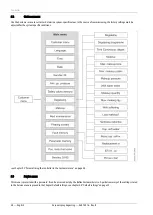
Page 38: ...ttings must be adjusted for the system specific conditions see chapter 9 5 Parametrising the controller in the Customer menu on page 40 9 3 Service menu This menu is protected with a password It can b...

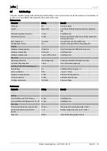
Page 39: ...with With water meter yes Maximum makeup time 20 minutes Only Magcontrol Maximum makeup cycles 3 cycles within 2 hours Only Magcontrol Degassing Degassing programme Interval degassing Continuous oper...

Page 40: ...s for Day Month and Year to the current date The date of an alarm will be stored in the fault memory Date Magcontrol Select this setting if you want to realise a pressure dependent automatic make up i...

Page 41: ...chapter 4 6 Optional equipment and accessories on page 13 This is the prerequisite for the make up quantity monitoring and the operation of a softening system With water meter no A contact water mete...

Page 42: ...n set in the With softening menu option Manufacturer specification for the replacement interval of the softening cartridges regardless of the calculated soft water capacity The system displays the Sof...

Page 43: ...are stored with fault type date time and fault code See the chapter Messages for more information about the ER messages ER 01 xx Switch to the parameter memory or into the next main menu option Parame...

Page 44: ...t Cause Remedy Alarm reset 01 Minimum pressure Yes For Magcontrol setting only Set value not reached Water loss in the system Fault PU vacuum pump Expansion tank defective Check set value in the Custo...

Page 45: ...cable for damage Check the pressure sensor Quit 10 Maximum pressure For Magcontrol setting only Set value exceeded Check set value in the Customer or Service menu Set the tripping pressure of the saf...

Page 46: ...Replace the I O module Check the connection between option card and controller Replace the option card 31 EEPROM defective Yes EEPROM defective Internal calculation error Inform Reflex Customer Servi...

Page 47: ...g installation removal or maintenance work at the connection points The Servitec must be serviced annually or after 16 000 degassing intervals whichever comes first Note This corresponds to a continuo...

Page 48: ...tion test of the vacuum pump see chapter 9 5 Parametrising the controller in the Customer menu on page 40 Annually Clean the dirt trap see chapter 10 2 1 Cleaning the dirt trap on page 49 Depending on...

Page 49: ...the ball valve upstream of the ST 1 dirt trap 3 Slowly unscrew the cap with the dirt trap insert at the dirt trap to release any residual pressure in the pipeline section 4 Pull the mesh from the cap...

Page 50: ...acuum spray degassing 06 07 2016 Rev B 10 3 Maintenance certificate All maintenance tasks have been completed according to the Reflex Installation Operating and Maintenance Manual Date Service organis...

Page 51: ...oggles CAUTION Risk of burns on hot surfaces Hot surfaces in heating systems can cause burns to the skin Wait until hot surfaces have cooled down or wear protective safety gloves The operating authori...

Page 52: ...2 Manual mode on page 35 4 Open the CD 3 ways motor ball valve until you have attained equal pressure with the ambient atmosphere 5 Disconnect the power cable of the device from the power supply 6 Di...

Page 53: ...ervice Central customer service Central telephone number 49 0 2382 7069 0 Customer Service extension 49 0 2382 7069 9505 Fax 49 0 2382 7069 9588 E mail service reflex de Technical Hotline For question...

Page 54: ...tandards and set of rules Pressure Equipment Directive AD 2000 according to tank nameplate Pressure equipment Tank vacuum spray tube Article 4 Para 1 a i 2 dash Annex II diagram 2 with Accessories Art...

Page 55: ...Annex Vacuum spray degassing 06 07 2016 Rev B English 55 12 3 Guarantee The respective statutory guarantee regulations apply...

Page 56: ...Annex 56 English Vacuum spray degassing 06 07 2016 Rev B...

Page 57: ......

Page 58: ...SI1419enB 9125077 12 17 Reflex Winkelmann GmbH Gersteinstra e 19 59227 Ahlen Germany Telefon 49 0 2382 7069 0 Telefax 49 0 2382 7069 9588 www reflex de...

Reviews: