


Description of the device
4
—
English
Servimat M/L — 28.01.2021
3.5
Inadmissible operating conditions
The device is not suitable for the following applications:
•
Outdoor operation.
•
For use with mineral oils.
•
For use with flammable media.
•
For use with distilled water.
Note!
It is not permitted to make any modifications to the hydraulic system or
the circuitry.
3.6
Residual risks
This device has been manufactured to the current state of the art. However,
some residual risk cannot be excluded.
CAUTION
Risk of burns on hot surfaces
Hot surfaces in heating systems can cause burns to the skin.
•
Wear protective gloves.
•
Please place appropriate warning signs in the vicinity of the device.
CAUTION
Risk of injury due to pressurised liquid
If installation, removal or maintenance work is not carried out correctly, there is a
risk of burns and other injuries at the connection points, if pressurised hot water
or hot steam suddenly escapes.
•
Ensure proper installation, removal or maintenance work.
•
Ensure that the system is de-pressurised before performing installation,
removal or maintenance work at the connection points.
CAUTION
Risk of injury due to heavy device weight
The device weight may cause physical injury or accidents.
•
If necessary, work with a second person during assembly or disassembly.
CAUTION
Risk of injury when upon coming into contact with glycol containing water
Contact with glycol containing water in plant systems for cooling circuits can
result in irritation of the skin and eyes.
–
Use personal protective equipment (safety clothing, gloves and goggles,
for example).
4
Description of the device
4.1
Description
The Servimat is a pump-controlled pressure maintaining, make-up and
degassing station for heating and cooling water systems. The Servimat is
essentially a control unit with pump, vacuum spray pipe and at least one
expansion vessel. The expansion vessel is fitted with a membrane to divide the
vessel into an air space and a water space. preventing the ingress of atmospheric
oxygen into the expansion water.
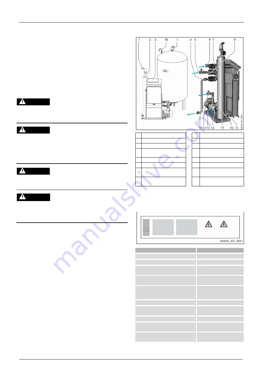
4.2
Overview
1 "DV" degassing valve
9
"FD" feed and drain cock
2 "PI" vacuum gauge
10 "VT" vacuum spray pipe
3 Control Touch controller
11 Insufficient water switch
4 Inlet to the expansion vessel
12 Connection from the expansion
vessel
5 Gas-rich water inlet
13 3-way motorized ball valve
6 Make-up connection
14 Degassed water outlet
7 2-way motorized ball valve (in
total 3x)
15
“PU” horizontal pump
8
“ST” dirt trap
16
“VE” pressure compensation
elbow
4.3
Identification
The nameplate provides information about the manufacturer, the year of
manufacture, the manufacturing number and the technical data.
Information on the type plate
Meaning
Type
Device name
Serial No.
Serial number
min. / max. allowable pressure P
Minimum/maximum permissible
pressure
max. continuous operating temperature
Maximum temperature for
continuous operation
min. / max. allowable temperature / flow
temperature TS
Minimum / maximum permissible
temperature / TS flow
temperature
Year built
Year of manufacture
min. operating pressure set up on shop floor Factory set minimum operating
pressure
at site
Set minimum operating pressure
max. pressure saftey valve factory - aline
Factory set actuating pressure of
the safety valve
at site
Set actuating pressure of the
safety valve


