Fillcontrol Auto Make-up and degassing
06.07.2016 - Rev. B
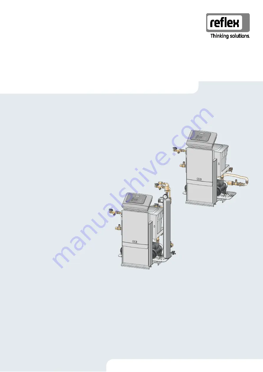
Fillcontrol Auto 2P Fillcontrol Auto 2PS
GB
Operating manual
Original operating manual
Page 1: ...Fillcontrol Auto Make up and degassing 06 07 2016 Rev B Fillcontrol Auto 2P Fillcontrol Auto 2PS GB Operating manual Original operating manual...
Page 2: ......
Page 3: ...Type code 11 4 4 Function 12 4 4 1 Fillcontrol Auto 2P 12 4 4 2 Fillcontrol Auto 2PS 13 4 5 Scope of delivery 15 4 6 Optional equipment and accessories 15 5 Technical data 16 5 1 Electrical system 16...
Page 4: ...36 8 1 1 Automatic mode 36 8 1 2 Manual mode 36 8 1 3 Stop mode 37 8 1 4 Summer operation 38 8 1 5 Restarting 38 9 Controller 39 9 1 Operator panel 39 9 2 Configuring settings in the controller 40 9 2...
Page 5: ...person installing this equipment or performing any other work at the equipment is required to carefully read this manual prior to commencing work and to comply with its instructions The manual is to...
Page 6: ...The sign in combination with the signal word Warning indicates imminent danger failure to observe the safety information can result in death or severe irreversible injuries CAUTION Damage to health T...
Page 7: ...ion of your country for personal protective equipment required 3 4 Intended use The devices must be operated only in a facility system with static pressure maintenance The devices may be used with the...
Page 8: ...cluded CAUTION Risk of burns on hot surfaces Hot surfaces in heating systems can cause burns to the skin Wear protective gloves Please place appropriate warning signs in the vicinity of the device CAU...
Page 9: ...spray pipe and convey it into the plant system System separator tank for makeup with water The system separator tank separates the makeup system from device The float valve in the system separator tan...
Page 10: ...e up and degassing 06 07 2016 Rev B 4 2 Overview 4 2 1 Fillcontrol Auto 2P 1 Operating unit 3 Pump 2 Control cabinet 4 System separator vessel 4 2 2 Fillcontrol Auto 2PS 1 Operating unit 4 System sepa...
Page 11: ...ntinuous operating temperature Maximum temperature for continuous operation min max allowable temperature flow temperature TS Minimum maximum permissible temperature TS flow temperature Year built Yea...
Page 12: ...eparator tank ensures a water supply from the make up system To prevent potential dry running an insufficient water switch in the system separator tank will shut down the pumps if required The device...
Page 13: ...her gas enriched water from the plant system is degassed in the vacuum spray pipe or water from the system separator tank is added to the vacuum spray pipe The float valve in the system separator tank...
Page 14: ...turned from the vacuum spray tube to the plant system via the pumps Here it is able to dissolve gases 3 Discharge The pumps shut down The system continues to inject and degas water in the vacuum spray...
Page 15: ...nt for completeness and damage 2 Please notify us immediately of any transport damage Basic make up equipment The pre wired device Operating manual 4 6 Optional equipment and accessories The following...
Page 16: ...illcontrol Auto 2P 500 230 50 10 2 Optional Fillcontrol Auto 2PS 500 230 50 10 2 Optional 5 2 Dimensions and connections Type Weight kg Height mm Width mm Depth mm Device connection System connection...
Page 17: ...n points if pressurised hot water or hot steam suddenly escapes Ensure proper installation removal or maintenance work Ensure that the system is de pressurised before performing installation removal o...
Page 18: ...pon receipt of the goods check the shipment for completeness and possible transport damage 2 Document any damage 3 Contact the forwarding agent to register your complaint 6 2 Preparatory work Preparin...
Page 19: ...on tank the device must be installed in the vicinity of the tank To ensure that the required filling pressure for water make up is recorded by the pressure transducer in the device The filling pressur...
Page 20: ...perties Comply with the following instructions The device is installed sufficiently close to the diaphragm expansion tank You ensure so that the pressure sensor is able to measure the filling pressure...
Page 21: ...the filling level of the diaphragm expansion tank When the required filling pressure for the facility system drops below the minimum value the pressure transducer sends a signal to the device controll...
Page 22: ...systems with static pressure maintenance the pressure transducer in the device monitors the water make up into the facility system When the filling pressure for the facility system drops below the mi...
Page 23: ...to the device Fillcontrol Auto 2P Make up line 1 to the facility system Proceed as follows 1 Ensure the permissible water temperature at the connection to the facility system 2 For the connection not...
Page 24: ...y that the main circuit board is voltage free For the electrical connection you must differentiate between an operating unit and a control cabinet 1 Covers of the operating unit folding RS 485 interfa...
Page 25: ...ses X0 2 N X0 3 PE 4 Makeup 230 V Y1 Is installed Fillcontrol Auto 2PS 5 N 6 PE 13 Floating signal contact 1 User supplied optional 14 23 Group message floating NC User supplied optional 24 COM 25 NO...
Page 26: ...PE 55 Expansion circuit board GND Voltage supply Fillcontrol 2P 56 24 V 13 Relay N O 1 COM Optional relay output 14 A1 59 Relay N O 2 COM Optional relay output 60 A2 61 Relay N O 3 COM Optional relay...
Page 27: ...l plan operating unit 1 Supply 3 RS 485 interface 2 I O interface Terminal number Signal Function Wiring X1 1 10 V AC 10 V supply Factory 2 3 FE X2 1 GND I O interface Interface to the main circuit bo...
Page 28: ...d commissioned in accordance to the instructions provided in the Operating Manual The settings in the controller match the local conditions Note When any factory set values of the device are changed y...
Page 29: ...minimum operating pressure for the controller Calculate the P0 minimum operating pressure During the start routine of the controller enter the value for the minimum operating pressure The controller...
Page 30: ...ion 2 Slowly open the shut off valve in the intake line to the pump The collector and the pumps are filled with water from the system separator tank via the intake line Fillcontrol Auto 2PS 1 Fill the...
Page 31: ...e of the safety valve This value may be the same as the release pressure of the facility system safety valve Safety valve pressure 4 Change the flashing display items for Hour Minute and Seconds to th...
Page 32: ...10 seconds Record the vacuum value displayed at the vacuum gauge 4 Observe the vacuum gauge 1 for approximately 10 minutes The pressure must not change If the pressure has increased check the device...
Page 33: ...tor panel to select P1 or P2 on the display The selected indicator P1 or P2 flashes to visually indicate the selected pump 2 Press OK on the controller s operator panel The selected pump is switched o...
Page 34: ...er calculates the required filling pressure The system is filled with water As soon as the filling pressure has been attained the controller automatically stops the filling process If the maximum fill...
Page 35: ...tion The Auto LED at the operator panel illuminates to visually signal automatic operation Note For Fillcontrol Auto 2PS during commissioning continuous degassing is automatically activated to remove...
Page 36: ...nuous operation The controller monitors the Automatic mode functions Note For Fillcontrol Auto 2PS during commissioning continuous degassing is automatically activated to remove any residual free or d...
Page 37: ...n and the displays shows P1 or P2 or NS The display must show values of 3 bar for the pressure for the activated pump 3 Press OK on the controller s operator panel The pumps or the motor ball valve ar...
Page 38: ...er using a screwdriver Switch the pump to a zero volts state before turning the pump at the fan wheel with a screwdriver ATTENTION Device damage due to pump start up Pump damage may occur when the pum...
Page 39: ...es green in Manual mode The Auto LED is not illuminated when the system is stopped 10 Pump The Pump LED illuminates green during pump operation 4 Menu Call up the Customer menu 11 Pump The Pump LED il...
Page 40: ...s to flash This time is used for entries in the fault memory Time This date is used for entries in the fault memory Adjust the Day Month and Year display when each begins to flash Date Berechnung P0 s...
Page 41: ...Only displayed if YES has been set in the With water meter menu option Make up quantity OK Delete meter yes The displayed make up quantity is set to 0 no The displayed water quantity is retained Only...
Page 42: ...20 alarms are stored with fault type date time and fault code See the chapter Messages for more information about the ER messages ER 01 xx Switch to the parameter memory or into the next main menu op...
Page 43: ...ar Tripping pressure for the safety valve at the heat generator in the system Degassing active only in Fillcontrol Auto 2PS 011 Degassing programme Continuous degassing Continuous degassing time 24 h...
Page 44: ...rential pressured added to the P0 minimum operating pressure Forced start of the pumps 24 h If the pumps are standing still for 24 hours they are forced to run for 3 seconds Pump run time exceeded mes...
Page 45: ...e Yes Set value not reached Water loss in the system Pump fault Expansion tank defective Check set value in the Customer or Service menu Check water level Check pump Check expansion tank 02 1 Insuffic...
Page 46: ...u Set value exceeded Severe water loss in the system Check set value in the Customer or Service menu Check the water loss in the plant system Quit 15 Makeup valve Contact water meter measures without...
Page 47: ...emory defective Contact the Reflex Customer Service Quit 34 Main board communication faulty Connecting cable defective Main circuit board defective Contact the Reflex Customer Service Quit 35 Digital...
Page 48: ...k of injury due to pressurised liquid If installation removal or maintenance work is not carried out correctly there is a risk of burns and other injuries at the connection points if pressurised hot w...
Page 49: ...adjust the initial pressure in the diaphragm expansion tank 10 2 Cleaning the dirt trap The dirt trap in the degassing pipe must be cleaned no later than after the expiry of the continuous degassing...
Page 50: ...before the next cycle starts 3 Subsequently check the following conditions With cold water the vacuum gauge must eventually show a value of approx 1 bar The Insufficient water message must not be disp...
Page 51: ...e up and degassing 06 07 2016 Rev B English 51 10 5 Maintenance certificate All maintenance tasks have been completed according to the Reflex Installation Operating and Maintenance Manual Date Service...
Page 52: ...surfaces in heating systems can cause burns to the skin Wait until hot surfaces have cooled down or wear protective safety gloves The operating authority is required to place appropriate warning sign...
Page 53: ...ember States relating to electromagnetic compatibility 2014 30 EU The following Standards have been applied to assess the products Deutsches Institut f r Normung European Standard 61326 1 2013 07 2 We...
Page 54: ......
Page 55: ......
Page 56: ...SI1667enB 9126331 02 18 Reflex Winkelmann GmbH Gersteinstra e 19 59227 Ahlen Germany Telephone 49 0 2382 7069 0 Fax 49 0 2382 7069 9588 www reflex de...