Reer AD SR2 Installation, Use And Maintenance Manual Download Page 7

7

INSTALLATION AND ELECTRICAL CONNECTIONS

+


The AD SR2 safety interface must be installed in an environment with at least
IP54 protection.

+


The voltage supplied to the AD SR2 interface must be of the FELV (Functional
Extra Low Voltage) 24VDC 

±±

20% type.

+


During installation, take care not to short-circuit terminals 7, 8, 10 and 11 on
the AD SR2 interface.

+


If connecting one barrier only, bring inputs that are not used (8 and 11)
to +24VDC.

The safety switch.

The system moves to 

BREAK 

status (output relays open) when the

safety switch 

(e.g. emergency pushbutton, safety limit switch)

,

connected as illustrated in the electrical diagrams on pages 4, 5, 6, 

is

opened. 

The switch must respond to the following specifications:

  2 N/C contact blocks connected mechanically.

  Release action to control contact opening.

  There must never be more than a 500msec delay between

both contacts in the switch closing; if that is not the case, the
interface moves to 

FAIL.

The interface can only restart 

(GUARD)

 after resetting the switch (with

the barrier clear).

+


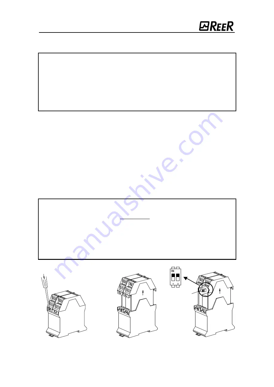
Should risk analysis regarding dangerous machinery authorize the use of a
safety switch with ONLY 1 N/C CONTACT (e.g. terminal 9 connected to +24VDC
or terminal 12 earthed), set both sections of the dip-switch (1) to ON (figure 5).
In that case, the test circuit for that specific safety switch will no longer
conform to EN 954-1 type 4.

+


If using a safety switch with ONLY 1 N/C CONTACT, terminal 9 must be used
(to +24VDC). Terminal 12 must be left open.

+


If the safety switch is not used, connect terminal 9 to +24VDC and terminal 12
to 0Vdc (dip-switch to OFF).

Figure 5

(1)

(PRESS LIGHTLY ON ALL
FOUR HOOKED COUPLINGS)

Summary of Contents for AD SR2

Page 1: ...SAFETY INTERFACE AD SR2 INSTALLATION USE AND MAINTENANCE HANDBOOK INDICE INTRODUCTION 3 OPERATING MODES 4 INSTALLATION AND ELECTRICAL CONNECTIONS 7 DIMENSIONS 10 TECHNICAL DATA 10 WARRANTY 11...

Page 2: ...2...

Page 3: ...ut of the K1 K2 feedback to check that these operate in safety The AD SR2 interface when connected to one or two type 4 photoelectric safety barriers certified to IEC 61496 1 2 standard equipped with...

Page 4: ...hrough the opening he she may remain in the danger zone without being detected use as trip device according to IEC 61496 Failure to comply with this rule may result in very serious risks for the perso...

Page 5: ...S K1 and K2 Control of external contactors K1 K2 can be activated in both operating modes If this control is to be used the set of normally closed and normally open ed contacts of the external contact...

Page 6: ...ar waiting for RESTART command ON Malfunction detected output relays open FAIL Red OFF Correct functioning ON K1 K2 malfunction detected output relays open FAIL K1 K2 Red OFF Correct functioning ON Ba...

Page 7: ...ntact blocks connected mechanically Release action to control contact opening There must never be more than a 500msec delay between both contacts in the switch closing if that is not the case the inte...

Page 8: ...ates the RESTART command The Restart command must be located outside the danger zone in a place from which the danger zone and the entire work area concerned are clearly visible The controls must not...

Page 9: ...ol contacts K1 1 and K2 1 terminal 13 must be able to switch a current of 20mA and a voltage of 24Vdc To increase the electrical life of internal relays A and B it is advisable to use anti disturbance...

Page 10: ...1 N C contact 20mA 24VDC Connections To terminal block with protection against reversal of polarity CLEAR output Imax 100mA Status indicators Led Guard Break Fail Fail K1 K2 Light Barr1 Light Barr2 Sa...

Page 11: ...s modifications adaptations not carried out by REER personnel tampering etc Accidents or impacts also due to transportation or causes of force majeure Other causes not to be ascribed to REER Repairs w...

Reviews: