

12
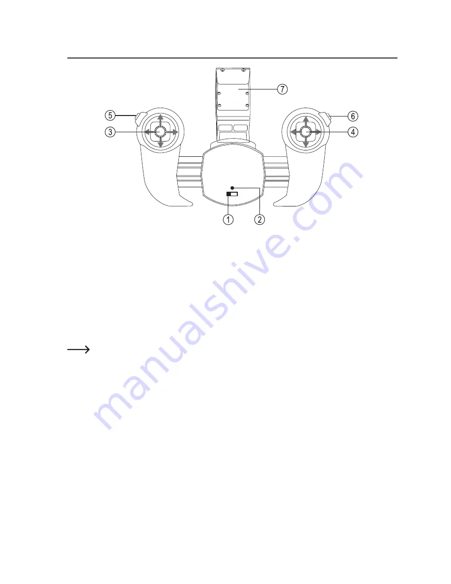
9. Operating Elements of the Transmitter
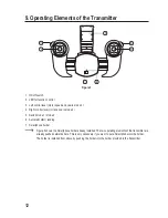
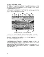
Figure 3
1 On/off switch
2 LED for function control
3 Left control lever (motor speed and yaw in mode 2)
4 Right control lever (roll and nod in mode 2)
5 Switch mode 1 / mode 2
6 Automatic start / landing
7 Smartphone holder
Figure 3 shows the Smartphone holder already installed. The two operating elements of the transmitter are
already pushed outwards here. This is only necessary if you want to put a Smartphone into the holder.
The holder is installed from above by pushing the holder into the holder provided in the transmitter.


