


www.
reefe
.com.au
Ascento Group Australia
©
AI.062020
P: 1800 807 604
ALARMS FOR SINGLE ASSEMBLY.
In case of simultaneous alarms, quit the automatic mode and go to manual mode, pressing the pushbutton
AUTOMATIC ON/OFF
(led light PUMP will
turn off). Using key
will be displayed the succesive alarms. Once visualized, for leaving the menu, press
ENTER
returning to
MANUAL
mode.
A1 DRY RUNNING
(
Failure verification
Final failure)
DESCRIPTION: if the system detects dry running during more than 10 seconds, it will stop the pump and the ART (Automatic ResetTest) will be
activated.
SYSTEM REACTION: after 5 minutes ART system will start again the pump during 30 seconds, trying to restore the system. In case of persistent lack of
water, it will try it again every 30 minutes for 24 hours. If after all these cycles , the system still detects lack of water, pump will remain permanently out
of order until the damage will be repaired.
SOLUTION: dry running, it has been activated the safety system: you should verify the feeding of the hydraulic network. The pumps can be primed
using the push-button START/STOP ( the led light AUTOMATIC should be off, if it is not, press the push-button to disable it).
Special case:
if the pump cannot provide the programmed pressure (configuration mistake) the unit reacts as it was dry-running.
Special Case 2:
this device manages the dry running control through the nominal current consumption of the pump. It must be verified the introduced
current consumption in the setup menu.
A2 OVER-INTENSITY
(
Failure verification
Final failure)
DESCRIPTION: the pump is protected against over currents by mean of the intensity values established in the installation menu. These over currents are
produced generally by dysfunctions in the pump or in the electric supply.
SYSTEM REACTION: when detecting the thermal failure, the pump will be automatically stopped. The system will try again to restart the pump when
the demand of consumption require it. The control system will carry out 4 attempts in this circumstances. If the system remain locked after the 4th
attempt, the pump will remain definitively out of order.
SOLUTION: verify the state of the pump, for example the impeller could be blocked. Verify intensity values introduced in the configuration menu. Once
the problem have been solved the operation will be restored going to the “SET UP” menu ( see the chapter configuration) and configuring the adequate
intensity values.
A3 DISCONNECTED
P. (
Final failure)
DESCRIPTION: the device has an electronic safety system in case of no load detection.
SYSTEM REACTION: the device is disconnected.
SOLUTION: the wound of the motor and the pump consumption should be verified. Once the problem have been solved the operation will be restored
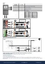
going to the "SET UP" menu (see the chapter configuration) and introducing the adequate intensity values. Verify the fuses (see fig.3), in case of being
melt contact with technical service.
A5 TRANSDUCER
(
Final failure)
DESCRIPTION: the transducer damages are showed in the LCD screen.
SYSTEM REACTION: the device operation is interrupted.
SOLUTION: check the external pressure transmitter.
A6 EXCESSIVE TEMP
. (
Final failure)
DESCRIPTION: the system has a cooling device to keep the INVERTER in optimum working conditions.
SYSTEM REACTION: if an excessive temperature is reached the own system leaves the inverter out of service and as consequence the pump too.
SOLUTION: verify the temperature environment should be under 50 ºC. Contact with technical service.
A7 SHORTCIRCUIT
(
Final failure)
DESCRIPTION: the device has an electronic system for protection against short circuits as well as peaks of current.
SYSTEM REACTION: the pump stops and then it starts again -performing 4 successive attempts. If the problem is not solved, the pump will remain
definitively out of order.
SOLUTION: check the pump, if the problem persists, contact the technical service.
A8 OVERVOLTAGE - A9 UNDERVOLTAGE
(
Failure verification)
DESCRIPTION: the device has an electronic safety system against overvoltage’s and too low supply voltages.
SYSTEM REACTION: in case of overvoltage or undervoltage the system remains stopped until an adequate value of voltage is reached. In this case, the
system is automatically restored.
SOLUTION: check the electric supply.
ALARM INSTALLATION MASTER-SLAVE
A10 COMUNICA
(
Failure verification)
DESCRIPTION: If you have configured a Master-Slave system and communication cable is disconnected or there is a bad connection, the system stops.
SYSTEM REACTION: The Master-Slave system stops and starts to operate individually.
SOLUTION: Check the cable connection and if this is OK, check the connection inside the unit. Check the configuration of the Master-Slave system
(setup menu).
DESCRIPTION: blank screen.
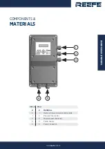
SOLUTION: check the electric supply. In case of being in right conditions, the general fuse, located in the main plate (fig 1) should be verified.