


www.
reefe
.com.au
Ascento Group Australia
©
AI.062020
P: 1800 807 604
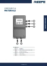
ALARMS FOR GROUP ASSEMBLY:
The alarms for assembled devices, are like those of the individual one with the specific particularities of operation with 2 communicated devices. De-
pending on the system´s reaction there are 3 types of alarm:
1
.-
COMMUNICATION FAILURE:
not any alarm is activated. Both devices continue operating independently. There will not be flashing led-light in any
unit.
2 .- DRY RUNNING OPERATION:
if there is a lack of water alarm in a single pump, the other one assumes the role of “main device”, if there is an
over-demand during next operating cycles, the system will try to restore the device in failure. If the device is restored in these conditions, then it will
be also restored the alternated operating mode. If there is lack of water on both devices, the system will activate the ART system in the MASTER unit.
3 .- REST OF ALARMS:
If the alarm has occurred in a single device, the other will act as “main device”. The system will try to restore the disabled
device only in case of over demand, after 4 successive attempts without success the device is turned off, it should be restored manually. In case of
alarms in both devices the system performs 4 restore attempts, if it fails the system is disabled.
To restore manually a device disabled by an alarm push
AUTOMATIC ON / OFF
in MASTER device and then
ENTER
in the device with the alarm.
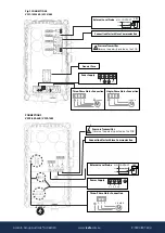
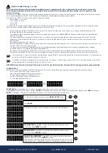
REGISTER OF OPERATION DATA AND ALARMS.
By using simultaneously MENU +
during 3” is acceded to
REGISTER OF OPERATION DATA AND ALARMS
, by mean of
ENTER
we can advance through
the sequence, once finished the sequence it returns to the main display. This is all the sequence:
•
REGISTER HOURS. Counter of total time that the pump has been operating.
•
REGISTER STARTS. Number of cycles of operation, a cycle is a start and a stop.
•
REGISTER SWITCH. Number of connections to the electric supply.
•
MAX PRESSURE. Maximum pressure reached by the installation. It allows the detection of water hammer.
•
ALARM COUNT. SHORTCIRC. Number of short circuit alarms.
•
ALARM COUNT I MAX. Number of overcurrent alarms.
•
ALARM COUNT. TEMP. Number of alarms by excessive temperature.
•
ALARM COUNT DRY RUN. Number of dry-running alarms.
All the records are saved even if the device has been disconnected from the electric supply.
C Y C L E S
X X
D R Y
R U N
X X
S H O R T C I R
X X
R E G I S T E R
S W I T C H
O N
X X
T E M P E R A T
X X
H I G H
V O L T
X X
U N D E R V O L
X X
H O U R S
X X
I N T E N S I .
X X
MENU+
ENTER
ENTER
ENTER
ENTER
ENTER
ENTER
ENTER
P s e t
4 , 0
P b a r
3 , 9
P s e t
4 , 0
P b a r
3 , 9