


www.
reefe
.com.au
Ascento Group Australia
©
AI.062020
P: 1800 807 604
BEFORE INSTALLATION AND USE, READ THE FOLLOWING INSTRUCTIONS CAREFULLY. THE MANUFACTURER DECLINES ALL RESPONSIBILITY IN
THE EVENT OF ACCIDENT OR DAMAGE DUE TO NEGLIGENCE OR FAILURE TO OBSERVE THE INSTRUCTIONS DESCRIBED IN THIS MANUAL OR IN
CONDITIONS THAT DIFFER FROM THOSE INDICATED ON THE DEVICE.
OPERATION
A wall-mounted automatic control device designed for the single and three-phase pumps automation, with an electronic system managed by a software
responding to the rigorous requirements of efficiency and safety of the most important pump manufacturers. It includes a frequency inverter that regu-
lates the speed of the pump to keep constant the pressure independently of the flow given.
The system incorporates an LCD screen where the parameters configuration is very easy and intuitive. Once the configuration parameters are set, the
device manages the start-up of the pump and the frequency inverter. It assures a constant pressure and an important costs reduction because at any
time the control will feed the system with the right and necessary output, obtaining a maximum energetic efficiency. In order to establish the optimal
pressure in the installation is suitable to consider following criteria:
Hm:
Max. water column height in m. It depends on the number of floors and it corresponds to the height from the pump to the last floor. Every 10 m of
height corresponds approximately to 1 bar (0.98) bar.
Pw:
Available minimum pressure in last floor (usually 1.5 bar).
Pc:
Pressure drop. It can be considered with a simplified criterion as 0.033 bar/m.
Pr min:
Minimum resultant pressure. It is the sum of the previous pressures and it will be the operating pressure of the pump.
Example for 5 floors building (15 m) with pump placed at level 0:
Hm = 15 m @ 1.5 bar Pw = 1.5 bar Pc=15 x 0,033 bar @ 0.5 bar Prmin = 1.5 + 1.5 + 0.5 = 3.5 bar
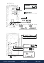
MASTER AND SLAVE OPERATION
The group MASTER-SLAVE is constituted by a device configured as MASTER - responsible of the group´s control - and a device configured as SLAVE
controlled by the master device.
Due to the alternating sequence of operation, the one configured as MASTER began the first cy cle as MAIN device - its pump is the first to start - but in
the next cycle it becomes SECONDARY - its pump is the second to start - and so on. Therefore, the fact that a device is configured as MASTER involves
control of the group but this fact does not avoid its operation alternately as SECONDARY device. Each device must be provided with its own pressure
transmitter.
MAIN CHARACTERISTICS
•
Wall-mounted frequency inverter for the pump control.
•
Control and safety system against over-intensities.
•
Control and safety system against dry operation.
•
ART
function (Automatic Reset Test). If the device has been stopped due to the action of the safety system against over-current, the
ART
tries to
connect the pump, with a programmed periodicity because the water supply could have been restored
•
Automatic restore system after an interruption of power supply. System is activated in AUTOMATIC mode keeping the configuration parameters
(see “CONFIGURATION” chapter).
•
External pressure transducer (4..20 mA) under demand.
Possibility of communication with another device to operate in MASTER & SLAVE regime.
•
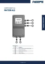
Control panel:
-
LCD screen, for alarm menu with permanent pressure indication.
-
START/STOP push-button to act by hand each one of the pumps
-
ENTER pushbutton to save data in memory.
-
ON/OFF pushbutton to change rom AUTOMATIC to MANUAL mode or vice versa.
-
MENU push-button
-
Keyboard for the access to programming menu.
-
Digital gauge.
•
Connections for detection of minimum water level in aspiration tank. This system is independent of the safety against dry operation. Is optional.
•
Register of operational controls: information about operating hours, counter of starts, counter of connections to the power supply.
•
Register of alarms: information about type and number of alarms since the starting up of the device.
CLASSIFICATION AND TYPE
According to EN: 60730-1 and EN:60730-2-6 this unit is a control electronic device for pressure groups, with flexible cable for permanent assembly type
Y, action type 1Y (transistor output). Operating value: flow 2.5 l/min. Degree of contamination 2 (clean environment). Software Class A.
Impulse rating voltage: cat II / 2500V. Applied temperature for the ball pressure test: enclosure (75ºC) and PCB (125ºC). Control circuit for AC motor
with cos fi
≥
0,6 (single-phase) and cos fi
≥
0,75 (3-phase).
According to EN 61800-3 this device is C2 class - C1 class under request.
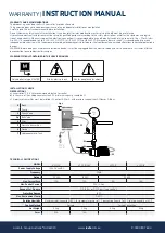
MECHANICAL INSTALLATION (fig. 2)
•
Store in a clean and dry environment, do not remove the unit from its packaging until it must be used.
•
The device must be installed in environments pollution grade 2 according to EN-60730-1.
•
The protection degree is IP55/IP65 depending on the model, therefore must be mounted in places protected from the rain.
•
Install the device in an upright wall, leaving at least 200 mm of space on its top and bottom to facilitate heat dissipation.
•
The unit will be anchored in the wall using the 4 holes of 7 mm in diameter located on its corners.
HYDRAULIC INSTALLATION (fig. 2)
Before proceeding with hydraulic connection, it is essential to install a non-return valve in the pump´s inlet.
In case of assembly in group, it must be mounted a collector for the communication of the devices water outputs. The inlet must proceed from a com-
mon origin.
For mounting the pressure sensor can be used any outlet G1/4 "at the pipe after the pump outlet.
•It must be installed an hydropneumatic tank of at least 5 l to avoid problems caused by leakages in the hydraulic net
•The device is provided with an automatic system that stops the pump if there is no demand in the installation. If you are in an installation where the
device does not stop the pump when there is no demand, this happens because there are leaks in the installation (tanks, faucet, check valves...). In these
cases, it can be used the frequency minimum value like a frequency stop. (see CONFIGURATION)
•PROCEDURE: Open a faucet of the installation and set the desired minimum flow. With this flow, visualize in the screen the frequency at which the
pump is rotating. Set the minimum frequency to the frequency displayed on the previous screen.