


www.
reefe
.com.au
Ascento Group Australia
©
AI.062020
P: 1800 807 604
L
N
L
~3
W V U
~1
V U
4..20mA
COM
LEV
FAN
N
24 V DC
24 V DC
24 V DC
15 V DC
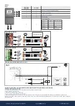
Connection Master&Slave Communication
Pressure Transmitter
Observe the polarity printed on the PCB.
External Level Probe
MAX.
MIN.
LEV
N.O. CONTACT
General Fuse
Power Supply
U
V
~1 240 V
M
Single-Phase Motor Connection
Three-Phase Motor Connection
U
V
W
~3 240 V
M
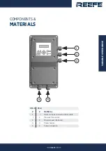
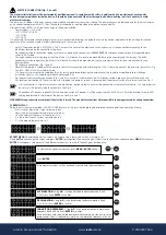
Fig. 3 CONNECTIONS
VSC1-12W-240 | VSC1-10W
15 V DC
24 V DC
~3x415 V
L1 L2 L3
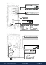
Pressure Transmitter
Observe the polarity printed on the PCB.
CONNECTIONS
VSC3-9W-240 | VSC3-14W
Connection Master&Slave Communication
External Level Probe
MAX.
MIN.
LEV
N.O. CONTACT
Power Supply
Three-Phase Motor Connection
U
V
W
Y ~3 415 V
M