background image

reechcraft.com/powerlift   888-600-6160

49

6.2

   Preventive Maint Inspection Schedule

The preventive maintenance and inspection checks are listed and defined in Table 6.0. 
The table is divided into two parts: “Area” and “Interval”.  The component or function to 
be inspected is listed in the Area column and the interval at which time they are to be 
inspected is listed in the Interval column.

Note:


The checks and services listed in this schedule are not intended to take the place of 

any local or regional regulations that may pertain to this type of equipment, nor should 
the list be considered as all inclusive. Variances in interval times may occur due to the 
environment the machine is subjected to.

Inspection and Maintenance Codes:

         1.    Check for proper and secure installation.

 2.   No gouges, excessive wear, or dents showing.
 3.   Visually inspect for excessive wear, damage, cracks, or distortion.
 4.   Check for cracked or broken welds.
 5.   Check area is clean and free of debris.
 6.   Check for proper adjustment.

         7.   Check for proper operation. 

 8.   Check for proper spring back.
 9.   Check for signs of leakage.

        10.   Check for proper tolerances.
        11.   Check for proper specifications. 
         12.   Verify.
         13.   Perform.
         14.   Replace.
         15.   Inspect per Operator’s Safety Manual.

S MAINTENANCE

SECTION 

6

Summary of Contents for PowerLift PL65

Page 1: ...4027516 PL65 OPERATOR S SAFETY MANUAL...

Page 2: ...al and on the machine to alert you to potential personal injury hazards Understand and obey all safety messages that correspond with this symbol to avoid possible injury or death INDICATES AN IMMINENT...

Page 3: ...BE NOTIFIED IMMEDIATELY IN ALL INSTANCES WHERE OUR PRODUCTS HAVE BEEN INVOLVED IN AN ACCIDENT INVOLVING BODILY INJURY OR DEATH OF PERSONNEL OR WHERE SUBSTANTIAL PERSONAL PROPERTY DAMAGE OR DAMAGE TO T...

Page 4: ...n 10 Machine Safety Information 10 Fall Hazards 10 Electrocution Hazards 11 Tipping Hazards 12 Crushing and Collision Hazards 14 Safety Information 14 SECTION 2 PREPARATION INSPECTION 2 0 Introduction...

Page 5: ...4 1 Incident Notification 40 SECTION 5 GENERAL SPECIFICATIONS 5 0 Introduction 41 5 1 Decal Contents Locations 41 5 2 Specifications 43 Machine Specifications 43 SECTION 6 SERVICE MAINTENANCE 6 0 Int...

Page 6: ...6 5 Mast Track Inspection Procedure 52 Mast Track Wear 53 Mast Track Misalignment 53 Mast Track Connector Wear 53 Machine Log 54 SECTION 7 TROUBLESHOOTING 7 0 Introduction 55 Troubleshooting Procedure...

Page 7: ...t 19 2 3 MaximumTrack Wear 20 2 4 Location of Manual Descent Crank 20 2 5 Platform Mounting and Retaining Pins 21 2 6 Inspection Points for Straddle Base Option 22 2 7 Mast Connectors 24 3 0 Outrigger...

Page 8: ...ipment PPE for the conditions If there are any questions regarding safety training maintenance inspection application or operation of the machine please contact ReechCraft FAILURE TO COMPLY WITHTHE SA...

Page 9: ...operation outside of this range Machine performance may be affected in very hot or cold conditions Machine Inspection Before machine operation perform walk around inspections and function checks Refer...

Page 10: ...ft suspended by their cord from the platform Be sure to fully lower the platform completely and remove all power before leaving the machine No more than one person is allowed on the machine Only the o...

Page 11: ...ent Maintain distance from electrical lines apparatus or any energized exposed or insulated parts according to the minimum approach distance MAD as shown inTable 1 0 Allow clearance for machine moveme...

Page 12: ...This determination shall be made by a qualified person in accordance with employer local or governmental requirements for work practices near energized equipment DO NOT MANEUVERTHE MACHINE OR PERSONN...

Page 13: ...machine on floors bridges and other surfaces check allowable capacity of the surfaces Never exceed the maximum platform capacity Distribute loads evenly on the platform floor Keep the weight bearing f...

Page 14: ...an elevated platform Position barricades on the floor as necessary Safety Information Never allow personnel in the platform while moving or repositioning the machine This machine shall not be towed b...

Page 15: ...ical control must not operate this machine 2 1 Operator Requirements Before operating this machine the operator must read and comprehend this manual The operator must be familiar with Use and limitati...

Page 16: ...illegible decals are cleaned or replaced Refer to Section 5 1 for decal contents and locations Safety and Service Make sure a copy of the Operator s Safety Manual is enclosed in a weather resistant c...

Page 17: ...inspection and maintenance recommended by ReechCraft Consult local regulations for further requirements The frequency of inspections and required maintenance must be increased if the machine is expose...

Page 18: ...or cracks or corrosion especially at intersecting weld joints Make sure the bubble level is clean and functioning Be sure all four outrigger retaining pins are functioning properly See Figure 2 1 Figu...

Page 19: ...eck for visible cracks or corrosion Check guide rollers for visible wear and proper alignment Check to be sure all fasteners and interlock pins are tight and functioning properly See Figure 2 2 Gearbo...

Page 20: ...PowerLift by ReechCraft 20 Figure 2 3 MaximumTrack Wear 0 2 in 5 mm Figure 2 4 Location of Manual Descent Crank Manual Descent Crank PREPARATION INSPECTION SECTION 2...

Page 21: ...ings Input Hex Shaft Entry Gate Platform Retaining Pin Mount Pins Mount Pins Entry Gate Platform and Entry Gate Check to be sure that the mounting pins are not loose platform railing is undamaged plat...

Page 22: ...will need to look over additional items prior to use See Figure 2 6 Ladder Check for any cracked welds misshapen rungs or tubes Leg Adjustment Pins Check for any misshapen pins or housings Leg Adjustm...

Page 23: ...gger interlocks one per outrigger to help ensure each outrigger is bearing weight and stabilizing the machine To test this fully lower the platform to the bottom of the base then briefly run the drill...

Page 24: ...er angle positions securely See Figure 2 6 Locking Caster Wheels Be sure that all four caster wheels do not swivel or roll when brakes are applied See Figure 2 6 Figure 2 7 Mast Connectors Cam Lever C...

Page 25: ...aft PowerLift is a drill powered aerial work platform AWP The removable platform is mounted to an elevating climbing unit that combines up to four modular mast sections that are stacked and fixed to a...

Page 26: ...commended drill motor specifications for safe operation and best machine performance 1 10 7 9 8 2 3 6 4 MACHINE OPERATION SECTION 3 1 Climbing Unit 2 Manual Container 3 Platform 4 Gearbox 5 Platform E...

Page 27: ...e drill motor is in drill mode Figure 3 2 Typical Drill Motor USE ONLY CORDLESS OR DOUBLE INSULATED CORDED DRILL MOTORS DISCONTINUE THE USE OFTHE DRILL IF A FAULT IS DETECTED ENSURETHE DRILL MOTOR IS...

Page 28: ...t initiated by the operator Before operating the machine be sure the platform is fully lowered and the base is stable Be sure the machine is level and on a surface capable of supporting the intended l...

Page 29: ...onary surface capable of supporting the intended load directly under the desired work area Connect to an appropriate power source AC connect to a grounded 15A AC power supply Be careful the extension...

Page 30: ...ease the pin into the appropriate bracket lug micro adjustment Rotate the cam levers to horizontal position to finish securing the leg Be sure to secure the caster wheel brake to keep the base from mo...

Page 31: ...is safe to use and the chassis is level and stable with all four outriggers bearing weight Move the direction selector so the drill motor is in the forward clockwise position Stop using the drill mot...

Page 32: ...ts stowed position Figure 3 7 Joining Mast Sections 4 With the cam lever in the down position be sure the cam lever lock springs automatically into the locked position 1 Stack the mast ensuring that t...

Page 33: ...tor loses power or contains insufficient power to lower the platform For emergency operation please see Section 4 on emergency procedures Figure 3 8 Separating Mast Sections 4 Carefully return the mas...

Page 34: ...e swivel casters The floor is required to be smooth level and dry All outriggers must be installed corresponding to the number of masts and elevated temporarily during maneuvering only There can be no...

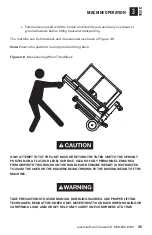
Page 35: ...ATTEMPTTOTILTTHE UNIT BACK OR RETURNTHETILTED UNITTOTHE UPRIGHT POSITION ON A FLAT AND LEVEL SURFACE CLEAR OF ANY PERSONNEL ENSURE A FIRM GRIP WITHTWO HANDS ONTHE HANDLE AND ENSURE WEIGHT IS DISTRIBU...

Page 36: ...rt When transporting the machine by vehicle it should be disassembled into its major components and each component secured separately Restrain each component of the machine securely during transport W...

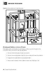
Page 37: ...rded drill loses power or the batteries of the cordless drill run out of sufficient charge to lower the platform THE CRANK IS DESIGNED FOR MANUAL DESCENT IN CASE OF LOSS OF POWER ONLY IT SHOULD NOT BE...

Page 38: ...power to the corded drill before the platform has fully descended Remove the drill and place it inside the platform Remove the manual descent crank from the mounting clip inside the platform Engage t...

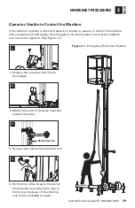
Page 39: ...ther personnel should deploy the emergency retraction system to lower the platform and rescue the operator See Figure 4 1 1 Remove the retraction winch from the chassis 2 Attach the winch to the base...

Page 40: ...formation Technical Safety and Engineering Department 845 34th St S Fargo ND 58102 customer service reechcraft com In USA 888 600 6160 Outside USA 701 280 5900 Failure to notify the manufacturer of an...

Page 41: ...4026586 CLIMBING UNIT B1 Manufacturer Nameplate 4027515 B2 Read Manual Tip Hazard 4026404 B3 Serial Number B4 Patent Marking 4026854 PLATFORM C1 Load Capacity 4027514 C2 Crush Hazard 4026003 C3 Read M...

Page 42: ...PowerLift by ReechCraft 42 Figure 5 0 Decal Locations A3 C5 C8 C4 C1 C7 C9 C6 C2 C3 D2 B1 B3 A1 A2 A4 A5 B2 D1 GENERAL SPECIFICATIONS SECTION 5...

Page 43: ...Drive with Integrated Drive Gear Brake Worm Drive with Integrated Drive Gear Brake Maximum Manual Force 52 5 lbs Maximum Wind Speed For Indoor Use Only Maximum Chassis Inclination 0 Degrees A Stowed L...

Page 44: ...PowerLift by ReechCraft 44 A B C D E F G H J I Figure 5 1 Machine Specifications 1 of 2 M H GENERAL SPECIFICATIONS SECTION 5 B A C D E F G J M I...

Page 45: ...reechcraft com powerlift 888 600 6160 45 GENERAL SPECIFICATIONS SECTION 5 Figure 5 2 Machine Specifications 2 of 2 H G M I J E F H K L...

Page 46: ...right to make specification changes without prior notification Contact ReechCraft for updated information MODIFICATION OFTHE MACHINE WITHOUT THE MANUFACTURER S APPROVAL IS A PROHIBITED PRACTICE AND A...

Page 47: ...E MAINTENANCE SECTION 6 Maintenance Safety FAILURETO COMPLY WITHTHE SAFETY PRECAUTIONS LISTED INTHIS SECTION COULD RESULT IN MACHINE DAMAGE PERSONAL INJURY OR DEATH 6 1 Machine Preparation Inspection...

Page 48: ...ree months or when purchased used The frequency of this inspection must increase as environment and frequency of use requires Reference the appropriate areas of this manual for service and maintenance...

Page 49: ...rtain to this type of equipment nor should the list be considered as all inclusive Variances in interval times may occur due to the environment the machine is subjected to Inspection and Maintenance C...

Page 50: ...1 2 3 5 Interlock 5 5 7 5 6 7 Track 3 3 3 15 Climbing Unit 5 3 5 1 3 5 7 Gearbox 3 7 9 3 7 9 1 3 7 9 Manual Descent Crank 1 1 12 1 3 12 Climbing Unit 7 1 7 1 3 5 10 7 Platform 1 4 5 1 4 5 1 3 4 5 7 P...

Page 51: ...nts Do not allow heavy objects to rest in an unstable position When raising a portion of the machine ensure that adequate support is provided Cleanliness The single most important item in preserving t...

Page 52: ...requently if used in a harsh environment or high duty cycle applications Inspections should be more frequent as the mast tracks approach the end of their useful lives The periodic inspection shall cov...

Page 53: ...e 6 0 MastTrack Misalignment Be sure that the track is aligned properly at the joint location If the track is bent or damaged in any way it must be replaced by a qualified mechanic before machine use...

Page 54: ...PowerLift by ReechCraft 54 MACHINE LOG RecordType 1 Examination 2 Test 3 Major Alteration 4 Repair Information Date RecordType Notes Table 6 1 Machine Log Machine Log SERVICE MAINTENANCE SECTION 6...

Page 55: ...enable the determination of the applicable corrective action The probable causes and corrective action should where possible be checked in the order listed in Table 7 0 It should be noted that there i...

Page 56: ...or more of the connector lock levers are in the open position interfering with the rollers Lower the platform to expose the last section of mast that was installed and check to be sure both levers ar...

Page 57: ...for a period of 90 days from the end user s original date of purchase the warranty period The end user warranty is non transferable by the end user and only applies to product manufactured after Septe...

Page 58: ...repair labor travel time or mileage for pickup and delivery shipping or freight costs or lost income for down time Additionally this end user warranty does not cover any duties taxes or environmental...

Page 59: ...WILL VOID THIS WARRANTY These warranties give the end user specific legal rights As the end user you may also have other rights which may vary from state to state Some states do not allow the exclusio...

Page 60: ...ReechCraft Inc 845 34th St S Fargo ND 58102 888 600 6160 reechcraft com powerlift...

Reviews: