background image

HIDEAWAY

ACTIVE SENSOR-FLUSH URINAL

Plumbers, please ensure a copy of the installation 
instructions is left with the end user for future reference

HIDEAWAY

ACTIVE SENSOR-FLUSH URINAL


2.0

Rough in wall preparation:

Note:

All plumbing installation work has to be carried out in accordance with AS/NZS 3500.

Installation requirements may vary, please check with your local authority.

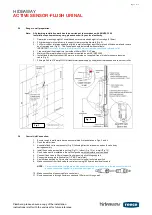
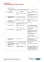
1. Determine mounting height of urinal based on recommended height to front edge (610mm)

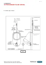
2. Fit timber noggin into wall cavity to support urinal mounting brackets (Fig. 3)

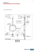
3. Fit 20mm copper inlet pipe supported rigidly in wall allowing at least 30mm proud of finished wall and remove 

burr from pipe end (Fig. 4). The flush pipe should be installed without offsets.

IMPORTANT: 

Accuracy is required to maintain 495mm centre distance between inlet and outlet

4. Trap outlet seal fits straight into the inside of 50mm DWV PVC pipe

5. Minimum 20mm water supply to this urinal is required as per AS/ NZS 3500

6. Install flexible electrical conduit (32mm minimum size, not supplied) free of kinks for sensor extension

cable (Fig. 4)

7. Fit single 240 volt 10 amp GPO for transformer/power supply unit adjacent to proposed location of controller


3.0

Control Unit Connection:

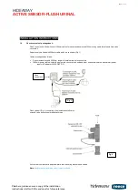
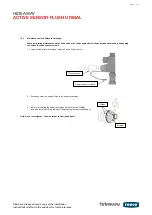
1. Ensure rough in wall details have been completed first as detailed in Figs. 3 and 4

2. Flush the water lines

3. Assemble flush valve components (Fig. 2) following directional arrow on solenoid valve body

during assembly

4. Install flush valve as required in-ceiling (Fig.11), in-duct (Fig. 12) or in-wall (Fig. 13)

5. Flush valve must be installed in the vertical position with the isolation valve closed

6. Connect flush valve to 20mm copper flush pipe using olive fitting supplied

7. Connect water supply to flush valve (1/2” BSP male inlet)

8. Peel off tape backing on Velcro strip to mount control unit directly into position

9. Make connection from flush valve to control unit using 1500mm solenoid valve cable.

NOTE:

Care must be taken to align pins inside each male connector with holes in female connector 

before 

pushing connectors together to prevent pins being bent.

10. Make connection of sensor cable to control unit.

11. Route sensor cable through flexible conduit and 100mm out through wall.

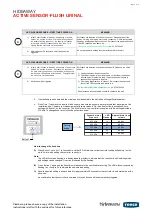
Fig. 3

Fig. 4

page 3 of 16

Summary of Contents for HIDEAWAY

Page 1: ...ions or queries during installation please contact Tech Support for phone assistance free call 07 3875 2465 We are happy to assist you Dear Customer This is the warranty by Reece Pty Ltd relating to t...

Page 2: ...d valve is fitted with 200mm cable and 2 pin connector Fig 1 Cables are supplied as follows Sensor extension cable 2500mm long with female male 4 pin connectors 1800mm power cable wired with single ma...

Page 3: ...mum size not supplied free of kinks for sensor extension cable Fig 4 7 Fit single 240 volt 10 amp GPO for transformer power supply unit adjacent to proposed location of controller 3 0 Control Unit Con...

Page 4: ...V flush with finished wall Fig 7 5 Fit kee seal to waste trap and lubricate before gently pushing into 50mm PVC DWV pipe so trap finishes flush with face of wall Fix waste trap to wall with single scr...

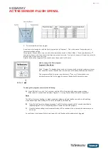
Page 5: ...r C Do not press buttons on the controller yet LED FLASH RESPONSE FIRST TIME POWER ON MEANING 1 Initial 2 short ashes followed by steady flashes at 1 second intervals After about 25 seconds of steady...

Page 6: ...ns in the male plug are not bent apart and line up with the holes in the female plug If required use your fingers to squeeze the plug and pins together 3 Check plug alignment and re connect Re connect...

Page 7: ...Schools This program will ush the urinal only after every 3 rd user or 15 minutes after use whichever comes rst It also triggers a janitor s ush after 48 hours of non use Button 2 To change the progr...

Page 8: ...onnection Now the ushing is suspended for 30 minutes 3 Add more of the cleaning agent to the water of the urinal After 30 minutes a ush will automatically trigger and the urinal is ready for use How t...

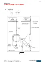
Page 9: ...instructions is left with the end user for future reference HIDEAWAY ACTIVE SENSOR FLUSH URINAL 8 0 Installation Types Use the following figures to provide installation guidance Fig 11 In ceiling ins...

Page 10: ...NSOR FLUSH URINAL Plumbers please ensure a copy of the installation instructions is left with the end user for future reference HIDEAWAY ACTIVE SENSOR FLUSH URINAL 8 0 Installation Types Continued Fig...

Page 11: ...HIDEAWAY ACTIVE SENSOR FLUSH URINAL HIDEAWAY ACTIVE SENSOR FLUSH URINAL 8 0 Installation Types Continued Fig 13 page 11 of 16...

Page 12: ...ically switch to Saver Mode 1 flush every minute when 4 users visit the urinal in less than 1 minute intervals no matter how many times used 1 minute of non use will reset the control unit back to Nor...

Page 13: ...sioning Look for 2 confirmation flushes to confirm urinal is functioning normally Problem fixed If problem cannot be resolved call 07 3875 2465 for assistance 5 seconds pause Pause then Temperature Se...

Page 14: ...ge is blocked Dynamic pressure has changed Un screw the solenoid cartridge and rinse out dirt out of the strainer see Section 1 Maintenance of the Solenoid Cartridge Check dynamic pressure and reset f...

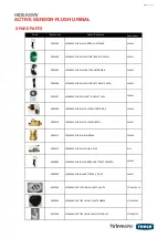
Page 15: ...enoid cartridge lubricate the two O Rings with a suitable tap O Ring lubricant Hydroseal tap lubricant or equivalent Note Do not over tighten The max torque is 1Nm hand tight 13 0 Spare parts 9503303...

Page 16: ...RINAL INLET OUTLET SEAL 200 034 9503309 HIDEAWAY URINAL SOLENOID CARTRIDGE 200 036 9503310 HIDEAWAY URINAL SOLENOID BODY 200 037 9503311 HIDEAWAY URINAL AIR BREAK 200 038 9503312 HIDEAWAY URINAL FLUSH...

Reviews: