1.
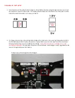
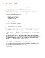
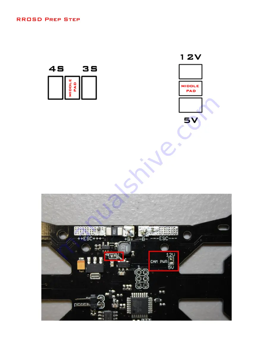
First check to see if the default solder bridges on CAM_PWR and battery voltage bridge selections are correct.
Each selection consist of 3 silver pads. The middle pad will already be connected to one of the pads on either
side with a solder blob when you receive your board.
2.
To change, simply remove the existing solder bridge with a solder wick. Use a very high temperature (400 C)
and thin tip being careful of nearby components. Apply solder to your iron and press tip to the correct pad
allowing solder to flow on to the middle pad and bridge
. Verify that all 3 pads are not bridged or you risk
destroying the RROSD!!!
VTX and CAM connections are both filtered. CAM voltage is strictly regulated but VTX
receives unregulated power from battery.
*Shown here with 4s bridged and 12V bridged.
Summary of Contents for STRIDER 250
Page 1: ...STRIDER 250...
Page 2: ......
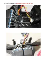
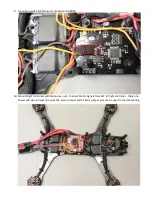
Page 16: ...7 Connection to CAM and VTX see warning section above if using 4s and 1 3Ghz...
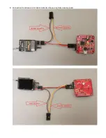
Page 17: ...8 Connection from Receiver to Flight Controller show using Frsky passing cppm...
Page 22: ......
Page 25: ......
Page 26: ...Coming soon...


