


AN-30 System User Manual
6
6
.
.
A
A
N
N
-
-
3
3
0
0
S
S
y
y
s
s
t
t
e
e
m
m
I
I
n
n
s
s
t
t
a
a
l
l
l
l
a
a
t
t
i
i
o
o
n
n
This section of the manual presents a basic overview of the steps required to install the
AN-30 terminal, outdoor transceiver, antenna and associated equipment.
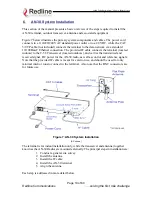
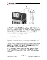
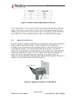
Figure 7 below illustrates the primary system components and cables. The power cord
connects to a 110/220/240 VAC standard power outlet or to a 48 VDC, while the CAT
5/UTP cable (not included) connects the terminal to the data network via a standard
10/100BaseT Ethernet connection. The provided IF cable connects the terminal (located
indoors) to the T-58 Transceiver (located outdoors), and carries the transmitted and
received signal, DC power for the AN-30 radio, as well as control and reference signals.
Note that the provided IF cable is meant for exterior use, and should be used for only
minimal interior runs to connect to the terminal. Also note that the BNC connectors are
for future use.
Figure 7: AN-30 System Installation
(AC shown)
The terminal is for indoor installation only, while the transceiver and antenna (together
known as the AN-30 Radio) are mounted externally. The principal steps in installation are:
1. Conduct a general site survey
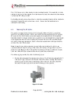
2. Install the antenna
3. Install the IF cable
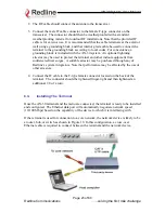
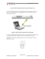
4. Install the AN-30 terminal
5. Align the antenna
Each step is addressed in more detail below.
Page 19 of 80
Redline Communications
…..solving the first mile challenge