background image


MegaPlus ES 1020 

User’s Manual 


Redlake MASD, Inc.       

 Page 

29 

91000134-001 Rev. A           


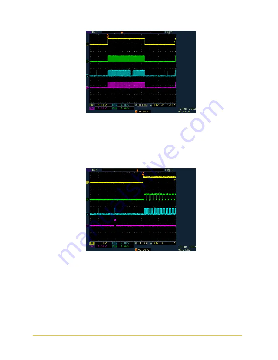
Triggered Timing 

Yellow = FVAL, Green = LVAL, Blue = Tap L data bit, Red - Tap R data bit 


Triggered Timing: Start of Frame 

Yellow = FVAL, Green = LVAL, Blue = Tap L, Red - Trigger 


Summary of Contents for MegaPlus ES 1020

Page 1: ......

Page 2: ...al applications any power supply connected to the camera must meet IEC 601 specifications Absolute Maximum Ratings Input Voltage 10 to 16V DC Storage Temperature 55 C to 70 C Recommended Maximum Ratings Input Voltage 11 to 14V DC Internal Operating Temperature 0 C to 85 C Recommended Operating Conditions Input Voltage 12V DC 0 5V Internal Operating Temperature 0 C to 65 C ESD The camera contains c...

Page 3: ...aunch Camera Control Software 8 Configure Camera Operating Mode Settings 8 4 ES 1020 CAMERA OPERATIONS MANUAL 11 CAMERA 11 LED s 11 Cables and Mating Connectors 11 5 CAMERA OPERATION 12 Command Descriptions 13 Camera Mode Descriptions 16 Trigger Exposure Modes 17 Internal Trigger timing 18 6 MAINTENANCE TECHNICAL SUPPORT AND WARRANTY 19 ROUTINE MAINTENANCE 19 TECHNICAL SUPPORT 19 WARRANTY 20 APPEN...

Page 4: ... exposure times as short as 35 microseconds for maximum flexibility and performance when capturing images of fast moving objects The triggered double exposure mode captures two images just microseconds apart With outstanding speed and resolution the MegaPlus ES 1020 is ideal for machine vision PIV semi conductor and electronic inspection microscopy and other applications requiring cost effective r...

Page 5: ...er The ES 1020 requires the use of a Power Adapter with 110 220V Cords which must be purchased separately through Redlake MASD Inc Lens es Because every application is different with varying focusing and field of vision requirements the ES 1020 is not shipped with lenses They must be purchased separately Minimum Recommended System Requirements Minimum Pentium II 233 MHz Processor At least 32 MB of...

Page 6: ...ra Link standards Before setting up the camera ensure that the frame grabber board and software have been installed Please follow the instructions outlined in the frame grabber manufacturer s documentation NOTE Frame Grabber Boards currently certified to operate with the ES 1020 Control Software at the time of this printing include Coreco Imaging PC CamLink Matrox Meteor II Camera Link Launch the ...

Page 7: ... Cable 1 First connect the Power Cable male end to the LEMO connector on the Power Adapter 2 Then connect to the female end of the Power Cable to the camera s Power connector 3 Finally connect the power adapter to a standard wall outlet using one of the power cables provided 4 When the camera is receiving power the G GR RE EE EN N Power LED will be on When the Y YE EL LL LO OW W Activity LED is bl...

Page 8: ...isition software Configure Camera Operating Mode Settings The Graphical User Interface offers access to all the programmable camera functions The various regions of the GUI are outlined below REFRESH Button This button is for updating the GUI to reflect what the camera is set to It is used whenever the camera and the software lose synchronization The following is an example of how the GUI can lose...

Page 9: ...ned triggered exposure is required Exposure time sec is set by sliding pointer along the slider bar Setting ranges from 0 000 to 0 1216 sec Triggered Manual Exposure TME works exactly as the TPE mode with the following exception the exposure may be extended by keeping the external trigger line asserted Triggered Double Exposure works exactly as the TPD mode with the following exception an addition...

Page 10: ...ns or combines pixel data The effect of binning is that the image will have lower resolution but higher SNR and by using vertical binning the image readout speed is improved The ES 1020 cameras implement horizontal and vertical binning as separate controls Vertical includes 5 radio buttons to allow the user to select Vertical Binning modes including V Bin x 1 V Bin x 2 V bin x 4 V Bin x 8 V Bin x ...

Page 11: ... indicates the microprocessor is ready to receive a command Cables and Mating Connectors Camera Link Located in the center of the rear panel of the camera is the CameraLink connector A similar connector is located on the frame grabber board and should be accessible on the back of the PC The CameraLink cable has 2 MDR 26 connectors Both ends of the cable are the same Power The ES 1020 receives powe...

Page 12: ...nsidered a slave device and never generates data without a read request The data packet formatting is described in detail below NOTE The checksum is calculated only on the 4 ascii characters comprising the Data Data Packets 1 ascii character 2 ascii characters 2 ascii characters 2 ascii characters 4 ascii characters 2 ascii characters 1 ascii character 1 ascii character Start Command Target Index ...

Page 13: ...K and re send the command with valid data and checksum If the Host detects an error it will re issue the command Host r tt ii dummy dummy dummy dummy cc camera issues Camera issues r tt ii data data data data cc NOTE no ACK Write Command Structure The camera parses the sequence byte by byte An invalid write command target index or checksum will cause the camera to issue a NACK otherwise the write ...

Page 14: ...x0001 1 0x0002 2 0x0004 4 0x0008 8 04 07 Camera Temperature Read 04 08 Camera actual exposure 10 bit number Read Write low speed version ES 1020 Read Write Low speed version ES 1020 0x0000 110µsec 0x03ff 76 32msec single tap mode 0x0000 83µsec 0x03ff 43 9msec dual tap mode 04 09 Partial Scan Enable Write 0x0000 Disable 0x0001 Enable 04 0a Partial Scan Start Line Read Write 0x0010 to 1200 04 0b Par...

Page 15: ...ed Bit 14 not used Bit 13 not used Bit 12 not used Bit 11 not used Bit 10 not used Bit 9 not used Bit 8 not used Bit 7 not used Bit 6 not used Bit 5 not used Bit 4 not used Bit 3 not used Bit 2 1 Trigger double exposure enabled Bit 1 1 IBIT complete Bit 0 1 Trigger manual exposure enabled Camera BIT status 06 00 Camera BIT Status Register 1 Read Bit 15 not used Bit 14 not used Bit 13 not used Bit ...

Page 16: ...m the table above Free Run Mode The camera continuously takes images at its mode dependent frame rate See Tables Appendix E The camera generates all synchronous timing including FVAL LVAL DVAL and pixel data and clocks In free run mode FRM the camera exposure is calculated in horizontal line times Thus exposure steps are equal to the camera horizontal line time plus a small overhead for the image ...

Page 17: ...gger line is sampled and if active the camera begins an exposure as set by the TPD register After the exposure period is complete the image is clocked out As the exposure is started the external strobe signal is asserted The external strobe signal can be used to activate a strobe light Trigger Programmed Exposure Mode Trigger Manual Exposure TME This mode works exactly as the TPE mode with the fol...

Page 18: ...se sequence requires a front pedestal then the transfer pulse and then a back pedestal Thus the TPD register cannot be used flash trigger sequences below the pedestal size 40us without external timing The range that TPD can be set to is 6 to 65535 dec 0001 to FFFF hex This results in a usable delay range from 30us to 138ms b Transfer Pulse Width TPW This register sets the width of the photodiode t...

Page 19: ...ly Outside the USA 858 481 8182 Fax 858 350 9380 Internet www redlake com Mailing Address Redlake MASD Inc 11633 Sorrento Valley Road San Diego California 92121 1010 For international customers please contact your authorized Redlake MASD Inc Distributor for information You may also contact one of the below listed service centers Roper Scientific BV Europe Middle East and Africa Telephone 31 347 32...

Page 20: ...damage caused by a failure to operate the Product in accordance with Redlake s written instructions including but not limited to environmental specifications listed in the Redlake user manual 2 damage caused by accidental user damage misuse or abuse of the Product 3 damage caused by the unauthorized attempted repair of or tampering with the Product by non Redlake personnel or 4 damage resulting fr...

Page 21: ...MegaPlus ES 1020 User s Manual Redlake MASD Inc Page 21 91000134 001 Rev A Appendix A Case Drawings units in inches ES 1020 Camera Dimensions ...

Page 22: ...utput signal on pin 2 is pass through of the incoming trigger If no trigger signal is sent from the frame grabber no signal will be present on pin 2 NOTE Externally triggering the camera may only be done via the Camera Link interface The Strobe and Trigger cables provide OUTPUT signals only Terminate unattached female BNC connectors with 50Ω terminators To connect the strobe trigger accessory cabl...

Page 23: ... to 1 to enable single tap operation Set to 0 to enable dual tap operation TRIGGER ENABLE Select Trigger mode of operation Setting this bit to 1 will cause the TG to enter the external trigger mode MANUAL EXPOSURE Manual trigger mode selection Set to 1 to enable single tap operation Set to 0 to enable dual tap operation TDE ENABLE Trigger Double Exposure Enable Set to 1 to enable TDE mode Set to 0...

Page 24: ...xposure and Control Register 2 15 14 13 12 11 10 9 8 CR2_3 CROSS HAIR ENABLE LONG_VBI N LVDS CLOCK x 2 EXP BIT 11 EXP BIT 10 EXP BIT 9 EXP BIT 8 7 6 5 4 3 2 1 0 EXP BIT 7 EXP BIT 6 EXP BIT 5 EXP BIT 4 EXP BIT 3 EXP BIT 2 EXP BIT 1 EXP BIT 0 EXP BIT 0 11 Manual Exposure LVDS CLOCK x 2 note set to 0 for normal operation set to 1 for 2x LVDS clock Set to 0 to Set to 1 to LONG V BIN Set to 0 to disabl...

Page 25: ...Save Camera State to Factory EEPROM Write dummy data correct checksum NA 03 03 Load Camera State from Factory EEPROM Read end and ack only NA 03 04 Load Current Camera State from ROM Read end and ack only NA 03 05 Read EEPROM Location Read 03 06 Reload Xilinx and restart camera Write 03 07 Save Tap Matching Array to Fact and User EEPROM Write 0x0000 Save Gain 1 to user and factory 0x0001 Save Gain...

Page 26: ...era BIT status 06 00 Camera BIT Status Register 1 Read 06 01 Camera BIT Status Register 2 Read Camera Configuration 07 00 Camera Model Read Write 07 01 Camera Revision Read Write 07 02 Camera Serial Number Read Write 07 03 Micro firmware version Read 07 04 Timing Generator firmware version Read Write 07 05 Overall Software Version Read Write 07 06 Clear EE Init flag Write ...

Page 27: ...34 4Mhz 29ns period 34 4Mhz 29ns period Frames Sec 28 37 48 83 H Active Pixels 1004 502 x 2 Taps H Count 1194 692 H Active Time 29 24us 14 65us H Sync Time 5 561us 5 561us H Line Time 34 9us 20 21us V Active Lines 1004 1004 V Count 1010 1010 V Active Time 34 98ms 20 31ms V Sync Time 269 3us 167 1us V Frame Time 35 24ms 20 48ms Free Run Timing Yellow FVAL Green LVAL Blue Tap L Red Tap R ...

Page 28: ...S 1020 User s Manual Redlake MASD Inc Page 28 91000134 001 Rev A Free Run Timing Start of Frame Yellow FVAL Green LVAL Blue Tap L Red Tap R Free Run Timing End of Frame Yellow FVAL Green LVAL Blue Tap L Red Tap R ...

Page 29: ...0 User s Manual Redlake MASD Inc Page 29 91000134 001 Rev A Triggered Timing Yellow FVAL Green LVAL Blue Tap L data bit Red Tap R data bit Triggered Timing Start of Frame Yellow FVAL Green LVAL Blue Tap L Red Trigger ...

Page 30: ... ES 1020 User s Manual Redlake MASD Inc Page 30 91000134 001 Rev A DVAL Timing Binning off Yellow FVAL Green LVAL Blue Tap L Red DVAL DVAL Timing 2X Horizontal Binning Yellow FVAL Green LVAL Blue Tap L Red DVAL ...

Page 31: ...MegaPlus ES 1020 User s Manual Redlake MASD Inc Page 31 91000134 001 Rev A DVAL Timing 4X Horizontal Binning Yellow FVAL Green LVAL Blue Tap L Red DVAL ...

Reviews: