background image

Oryginalna instrukcja obsługi

/

Original user’s manual

 REDATS L-121F 

41 


Summary of Contents for L-121F

Page 1: ...MOBILE ONE POST HYDRAULIC LIFT REDATS L 121F ORIGINAL USERS MANUAL version A 1 0 December 2021 Make sure to read this manual thoroughly before starting to work with the lift ...

Page 2: ...arning labels 32 1 5 Safety features 33 2 Transport and storage 33 3 Description of the lift 33 3 1 Elements of the lift 33 3 2 Technical data 34 4 Installation 34 4 1 Before installation 34 4 2 Installation 34 5 Operation rules 36 6 Maintenance and troubleshooting 39 7 Technical drawings 40 8 Electrical schematic diagram 42 9 Hydraulic schematic diagram 42 10 Exploded view 43 The EC Declaration o...

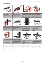
Page 3: ...s intended only for lifting the whole vehicle with a maximum weight not exceeding the maximum capacity of the jack The maximum capacity is shown on the plate on the jack Always make sure that the safety devices are engaged before any attempt to work on or near the vehicle To raise the car use only the lifting points recommended by the vehicle manufacturer Always lift vehicles using all four lift a...

Page 4: ...g labels on the lift remember that they must be visible at all times The manufacturer is not responsible for serious accidents and damage to people or other equipment caused by the use of the lift for purposes other than lifting vehicles Observe the use maintenance and precautions described in this manual ...

Page 5: ...vent of transport damage the ordering party must immediately inform the carrier about the problem When unpacking be careful not to injure people keep a safe distance when unfastening the straps and not to damage the lift itself be careful not to drop the jack part while unpacking The packed machine can be lifted or transported with the use of forklifts cranes or bridge cranes The machine is heavy ...

Page 6: ...rk area for the lift before its arrival it is recommended that the user operate the machine indoors 4 1 2 Power source The workplace must be equipped with a 230V power supply 4 1 3 Earthing The lift must be placed on a flat and hard ground made of cement or bricks with a load of the column position of 3t m2 4 1 4 Working area There should be approximately 2 500 mm of free space around the vehicle ...

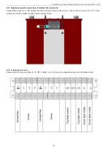
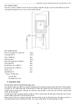
Page 7: ...imit switch and motor Connect the motor U V PE Install the limit switch as shown in the picture connect the two wires AV AV to the control box on the column as shown in the picture below 4 2 2 Connect power line Connect the three power cables L N PE 1 5mm2 to a box for each conductor as shown in the figure below ...

Page 8: ...Operation rules 5 1 Operation rules for mechanical moving system The movable single post lifter is provided with separate traveling mechanism Shake the tiller of the hydraulic movable set rear wheel forwards and backwards to make the column off the ground then you can push or pull the lifter On arriving the working site press the release handle to retract the wheel then the column lands on the gro...

Page 9: ...tion on the underside of vehicle 7 Press the button to make the vehicle be lifted for 10 15 centimeters 8 Stop lifting and check for secure four top positions of lifting pad 9 Check if the main lifting platform touches the vehicle chassis In normal lifting it should not touch the chassis 10 Pull the safety unlock handle to make the lifting platform unlocked 11 To adjust lifting pad turn it anticlo...

Page 10: ...Oryginalna instrukcja obsługi Original user s manual REDATS L 121F 38 Vehicle driving onto the lifter Schematic diagram of lifter lowering ...

Page 11: ... an oil leak is found check the source of the oil leak If oil is leaking from the cylinder the O ring mounted on the piston is worn and must be replaced specification is UHS65 Troubleshooting The lift arms cannot be raised 1 Check the power 2 Replacement any two wires of three phase wire and try to pick up again because the phase sequence of the power supply may not match the set phase sequence wh...

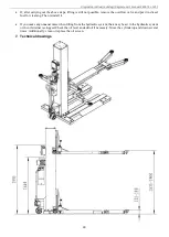
Page 12: ... valve and put it in diesel fuel for cleaning Then reinstall it If you make any unusual noise when lifting from the hydraulic system there may be air in the hydraulic system or the oil strainer is clogged Check the oil level and add oil if necessary Move the cylinder up and down several times Additionally clean or replace the oil screen 7 Technical drawings ...

Page 13: ...Oryginalna instrukcja obsługi Original user s manual REDATS L 121F 41 ...

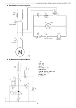
Page 14: ... s manual REDATS L 121F 42 8 Electrical schematic diagram 9 Hydraulic schematic diagram 1 Tank 2 Inlet filter 3 Oil pump 4 Motor 5 Start buffer valve 6 One way valve 7 manual pressure relief valve 8 Flow control valve 9 Relief valve 10 Cylinder ...

Page 15: ... Original user s manual REDATS L 121F 43 10 Exploded view 1 Cover 2 Limit switch 3 Control box 4 Bolt 5 Nut 6 Electric Power unit 7 Hydraulic movable set 8 Axle pin 9 Axle sleeve 10 Bar 11 Bolt 12 Allen head screw 13 Shim 14 column ...

Page 16: ...nual REDATS L 121F 44 15 Pulley 16 Bearing 17 Round nut 18 Pulley bracket 19 Pin 20 Screw 21 Leaf chain 22 Chain connector 23 Round pin 24 Cotter pin 25 Nut 26 Allen head screw 27 Chain connector 28 Shim 29 Spring washer 30 Nut 31 Hydraulic cylinder ...

Page 17: ...36 Pulley 37 Metal slider 38 Transverse arm 39 Longitudinal arm 40 Inner telescopic arm 41 Outer rotary arm 42 Pin shaft 43 Tooth block 44 Spring 45 Arm lock handle 46 lifting pad 47 Main lifting platform 48 Bolt 49 Gasket 50 Safety lock handle 50 Base plate 51 Pin shaft 52 Check ring 53 Axle sleeve 54 Bearing 55 Wheel ...

Page 18: ...rtificate number CE C 0220 19 21 04 5A issued on 2019 05 30 by Notified Body for Machinery Directive CCQS UK Ltd 5 Harbour Exchange Square London E14 9GE UK The product complies with the essential requirements of the 2006 42 EC Directive as well as the detailed requirements specified in harmonized standards of EN 12100 2010 EN 1493 2010 EN 60204 1 2006 AC 2010 This Declaration is a basis for apply...

Reviews: