background image

RAM-6021 Wired Router

85

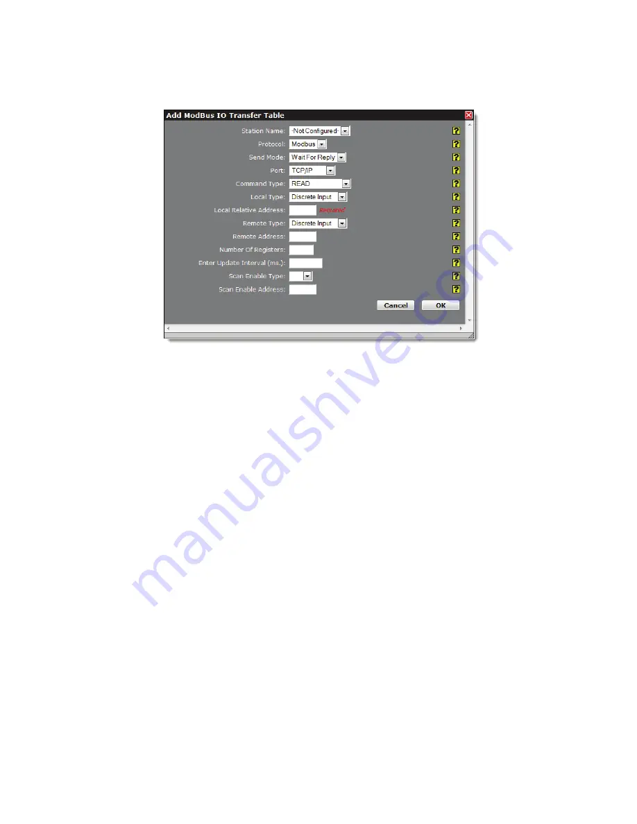
Automation Tab

Click


on


the


Add


button


to


configure


the


I/O


Transfer


for


the


remote


station


and


the


following


pop

up


window


will


appear:

Station


Name:


Name


of


the


remote


station


for


this


I/O


transfer.


This


option


lists


the


name


of


all


the


remote


stations


that


you


have


already


defined


and


configured


in


remote


station


table


entry.


Select


the


remote


station


name


that


you


want


for


this


I/O


transfer.

Protocol:


Modbus


is


currently


the


only


supported


protocol


used


for


I/O


transfers.

Send


Mode:


Mode


used


to


send


an


I/O


transfer.

Wait


for


Reply:


The


MODBUS


master


must


wait


for


an


I/O


request


that


it


has


sent


to


complete


before


sending


another


request


to


the


remote


station.

Rapid


Fire:


The


MODBUS


master


may


send


many


I/O


requests


to


a


remote


station


before


waiting


for


responses


from


the


remote


station.

Valid


Values:


Wait


for


Reply


or


Rapid


Fire

Port:


The


port


that


the


I/O


request


is


being


sent


across.


The


supported


ports


are


UDP/IP

,


TCP/IP


and


RS

232

.


If


UDP/IP


or


TCP/IP


port


is


used,


the


remote


station


selected


for


this


I/O


transfer


should


have


its


IP


address


defined.

Command


Type:


The


commands


used


for


I/O


transfers


are:

READ:


Used


for


reading


MODBUS


registers


from


the


remote


station.

WRITE:


Write


MODBUS


output


registers


to


the


remote


stations.

WRITE_SINGLE:


Write


a


single


MODBUS


discrete


or


analog


output


register


to


the


remote


station.


Note:


Only


an


option


when


writing


a


singe


discrete


output


or


single


analog


output.

Local


Type:


I/O


type


on


the


local


station.


See


Table2

 ‐ 

I/O


Types


and


Limits

.

Local


Relative


Address


(Required):


First


adress


of


the


local


I/O


used


for


the


I/O


transfer.


Valid


values


are


0


through


number


of


registers


configured


for


specified


I/O


type.

Remote


Type:


I/O


type


on


the


remote


station.


See


Table


2,


3,


4,


5

 ‐ 

I/O


Types


and


Limits

.

Remote


Address:


First


register


address


for


the


remote


I/O


used


for


the


I/O


transfer.


Valid


values


are


1

 ‐ 

65536.

Summary of Contents for RAM-6021

Page 1: ...www redlion net RAM 6021 Wired Router Software User Guide Version 1 0 Software Version 4 15 November 2013 ...

Page 2: ... 12 2 1 1 Organization 12 2 2 Status Tab 13 2 2 1 Summary 13 2 2 2 Network 16 2 2 3 Diagnostics 19 2 2 4 Syslog 22 2 2 5 Gather Stats 23 2 3 Admin Tab 24 2 3 1 Access Settings 24 2 3 2 System Time 25 2 3 3 Firmware Update 26 2 4 Network Tab 32 2 4 1 Interfaces 32 2 4 2 Firewall 38 2 4 3 Tunneling 52 2 4 4 DNS Settings 58 2 4 5 Static Routes 60 2 4 6 TCP Global Settings 61 2 5 Services Tab 63 2 5 1...

Page 3: ... VRRP Virtual Redundancy Protocol 106 2 7 3 Expert Mode 108 Chapter 3 Red Lion Support 111 Chapter 4 Software Licensing Terms and Conditions 112 Chapter 5 Warranty 113 Chapter 6 Appendices 114 Appendix A Red_Lion RAM MIB Contents 114 Appendix B Distributed Management Platform DMP 117 ...

Page 4: ... and the Red Lion router s Ethernet Port s Note If the Ethernet port s green LED is lit this indicates that the connection is running at 100Mb speed If the Ethernet port s green LED is not lit this indicates that the connection is running at 10Mb speed The yellow LED indicates the link status of the connection Yellow steady Link established Yellow flashing Data packets are being transferred ...

Page 5: ...M 6021 Wired Router 5 Setup PC IP Address 1 2 Setup PC IP Address 1 2 1 Open the Control Panel Click on Start and browse the Control Panel menu item The Control Panel should look similar to the following ...

Page 6: ...gs XP Network and Internet Connections Vista Windows 7 Network and Internet The displays should be similar to the following 1 2 3 Access Network Connection Settings Click on the link to access network connection settings XP Network Connections Vista Windows 7 Network and Sharing Center The display should look similar to the following ...

Page 7: ... Local Area Connection icon Vista Windows 7 View Status next to Local Area Connection The display should look similar to the following 1 2 5 Open Properties Click on Properties button Vista Windows 7 will display a popup window asking to confirm the operation Click on the Continue button The display should look similar to the following ...

Page 8: ...otocol Version 4 TCP IPv4 Click on the Properties button The display should look similar to the following METHOD 1 PC to Ethernet on RAM 6021 Select Use the following IP address and fill in the blank fields with the information below IP address 192 168 0 2 Subnet mask 255 255 255 0 Default gateway 192 168 0 1 Preferred DNS 192 168 0 1 Click OK The previous screen will appear Click OK ...

Page 9: ...k fields with the information below IP address 192 168 1 2 Subnet mask 255 255 255 0 Default gateway 192 168 1 1 Preferred DNS 192 168 1 1 Click OK The previous screen will appear Click OK Verify that you are connected to the RAM 6021 router Open a Command Prompt window on your laptop XP Start Run type in cmd and press the ENTER key ...

Page 10: ...ectivity to the router by running a ping to the IP Address of the Ethernet port you are connected to METHOD 1 PC to Ethernet on RAM 6021 Type in ping 192 168 0 1 and then press the ENTER key The display should look similar to the following METHOD 2 PC to ETH1 LAN Type in ping 192 168 1 1 and the press the ENTER key The display should look similar to the following This shows the connection is up an...

Page 11: ...on Router Login Instructions For the User Name enter admin all lowercase For Password enter the last six digits of the serial number located on the product label all lowercase Upon successfully logging in the following screen will appear Note The following information can be used for all series of router even if screen shots indicate other models Some models may have reduced options At this point ...

Page 12: ...ttings that connect the router to external interfaces The Net work tab is organized into six 6 major categories Interfaces Firewall Tunnelling DNS Settings Static Routes TCP Global Settings Services The Services tab is used to configure the various features of the Red Lion router These services include DHCP Server DHCP Relay SNProxy Settings SixView Manager SSH TELNET Server SNMP Agent Ping Alive ...

Page 13: ...stem pro cesses services running and system information It also allows review of the syslog update history and under diagnostic tools permits testing connectivity through the use of ping and traceroute 2 2 1 Summary This option will return the user to the System Summary home page On this page the system information and physical interface status are easily viewed ...

Page 14: ...n its IP address netmask and remote gateway as the default route It can also optionally obtain DNS server address via DHCP Select No to prevent the interface from obtaining address information via a DHCP servers You will be required to enter the IP address netmask and remote gateway addresses DNS information can be pro vided by navigating to the Network DNS Settings menu Enter IP Address Required ...

Page 15: ... network address is 192 168 1 0 with a netmask of 255 255 255 0 then it can communicate directly with any other device on that network with a range of addresses of 192 168 1 1 through 192 168 1 254 with 192 168 1 255 reserved for broadcast An address outside of that range is on a different network which would need to be accessed indirectly through a router That router would be the gateway to the n...

Page 16: ...s Arp Cache Firewall Rules Interfaces Routing Tables and Socket Statuses 2 2 2 1 ARP Cache The ARP Cache is a table which stores mappings between Data Link Layer OSI Layer 2 addresses and Network Layer OSI Layer 3 addresses This important information shows what connections are established to the router When you click on the ARP Cache menu item the following dialog window will appear ...

Page 17: ...n router If you are familiar with Linux and IPTables then this will be of great use Scroll through the list of rules to review the entire IPTABLES listing This information is used to track traffic being allowed and traffic being denied access to and through the Red Lion router 2 2 2 3 Interfaces The Interfaces menu item has three sections Summary Details and Multicast ...

Page 18: ...utes for the Red Lion router 2 2 2 5 Socket Statuses Sockets are end points to communication over the Internet Much like PBX phone systems where the IP address is the phone number and the port is the extension Every paired connected socket has a source IP port and a destination IP port There are three tables in the Socket Statuses dialog window TCP Only Conn Track and Socket Statuses All The TCP O...

Page 19: ...kets 2 2 3 Diagnostics The Diagnostics menu is sub sectioned into Ping Socket Test and Traceroute submenus These are useful in troubleshoot ing connectivity of the Red Lion router to the Internet or the Network the router is connected to 2 2 3 1 Ping The Ping menu item allows you to input an address either as an IP Address or a URL for testing the destination availability ...

Page 20: ...fers the option of using different interfaces to send the Ping through This is useful if you have a VPN Tunnel in place Testing the connection through the VPN Tunnel is required to verify connec tivity through the tunnel Choose the interface that the VPN Tunnel has listed for the Local Subnet end point i e if the Left Subnet is 10 100 100 0 24 and eth1 has 10 100 100 1 as its IP Address then choos...

Page 21: ...od test and this IP can be found in your routing table A commonly available internet server available to test against is 4 2 2 2 Source Interface field Select the source interface Choosing Unspecified will let the system choose the first inter face found with a route to the destination The Source Interface offers the option of using different interfaces to send the trace through This is useful sho...

Page 22: ...tomatic updating of the log file display The update interval can be selected using the Select Update Interval option provided in the field below the Auto Update one Manual updating is disabled while auto update is in effect The current filter and maximum lines to be displayed will be used Number of lines to display Select the number of lines to be displayed from one of the choices in the drop down...

Page 23: ...Only choose YES for this option if directed by the Technical Support Staff Include GWLNX Files Select YES to include all GWLNX configuration files The recommended setting for this option is YES Include All Network Files Select YES to include all networking related configuration files If using gaterconfigs to clone a unit note that this option will cause the network interfaces Including static IP a...

Page 24: ... 1 Access Settings The Access Settings menu item allows you to change how the unit s Web UI is accessed either by HTTP or HTTPS You can also change the passwords used to access the Web User Interface For security purposes it is recommended that the admin password be changed according to your internal policies Click on the Access Settings menu item and the following window will appear ...

Page 25: ...d field Note For a secure password choose one that is at least six char acters long which is not a common word and comprised of a mixture of upper and lower case characters and num bers Re enter the new password in the Confirm New Password field In the Confirm Admin Password which appears at the bottom of the dialog window once you enter a new password enter the current password Click on the Save ...

Page 26: ...rrent Time using the shown format Note The Hour field in on the 24 hour time clock range 00 24 This page verifies that the month day year hour min ute and seconds conform to expected inputs For example month range from 01 12 days range from 01 31 checks for limit according to month i e January has 31 days February has 28 or 29 depending on year etc Option 3 Use Local System Time Set the Sync to NT...

Page 27: ...d button for uploading the boot file Then once this step is completed select Root File System type and Browse to open root file image and click on Upload button for uploading the root file Click on the Install button Note This procedure could take anywhere from 6 10 minutes to complete WARNING It is important that the power to the unit is not interrupted as this could cause the unit to become corr...

Page 28: ...ort Web UI Master Configuration File Set your importing defaults for the configuration file Import File Handling Select Replace to completely replace the device configuration file with your import Select merge if you are importing a snippet of the main configuration Save Import file without applying changes If you want to save the new configuration without immediately applying it simply select YES...

Page 29: ...ml txt file and click on the Open button to populate the Browse window If needed you can change the file or remove it from the field by clicking the appropriate button Click on the Import button When import is complete a table will appear at the bottom of the dialog window list ing the modified files 2 3 3 2 Package Installation The Package Installation feature allows you to upload and install pat...

Page 30: ...dialog window appear Browse to the directory where the patch is located Select the filename to select the file Note Be sure to use only genuine Red Lion provided packages in the form of filename zip Click on the Open button to populate the Package File field and click on the Install button When install is com plete a table will appear at the bottom of the dialog window listing the modified files ...

Page 31: ... menu item and the following window will appear Restore Factory Default Click on the Restore button to restore the factory default settings A warning will appear read through the information and click OK The restore may take 2 5 minutes Reboot System Click on the Reboot button to reboot the device A warning will appear read through the information and click OK The reboot may take 2 5 minutes ...

Page 32: ...he administrator to configure the Ethernet ports of Red Lion routers to meet their needs Interfaces available may include eth0 WAN eth1 LAN and USB These will only be present if your hardware supports these interfaces These ports are auto sensing allowing for greater flexibility 2 4 1 1 eth0 and eth1 Internet Interfaces The configuration of the Ethernet ports is the same for eth0 and eth1 therefor...

Page 33: ...ration explicitly specified 10Mbps Half If selected the interface will communicate at 10 Mbps and half duplex 100Mbps Half If selected the interface will communicate at 100 Mbps and half duplex 100Mbps Full If selected the interface will communicate at 100 Mbps and full duplex Obtain Network Addresses via DHCP This field determines how an IP address will be assigned to the specified Ether net inte...

Page 34: ...outer to which the Red Lion router should forward all traffic for which it does not already know a specific route Take care to configure only one interface as the default route Use Remote Gateway as Default Route If YES is selected for this option the Red Lion router will forward any packets for which it does not have a route out through this interface This parameter should not be specified if the...

Page 35: ...uired This field is where you enter the Sub interface number The valid range is 0 99 and each aliased interface must be uniquely numbered The final sub interface name will then be in the form ethx y where x is the root interface number and y is the sub interface number Enter IP Address Required This field specifies the IP Address of the sub interface Enter Netmask Required This field specified the...

Page 36: ...tempt will be made to re connect to it using the new settings when possible Applying new settings to the interface may result in disconnection requiring reconnection using alternate methods Incomplete or incorrect network settings could render the device incommunicable and may require being able to connect either to the device directly or via the network to which it is attached Note To work with t...

Page 37: ...button will save your settings and apply them immediately To revert to the previous defaults click on the Revert button 2 4 1 3 Switch Control The purpose of the Switch Control function is to create a WAN LAN separation This gives the user the ability to create a divided network with additional capabilities Switch Control Settings Enable Split Lan This will alter the switch port allocations When d...

Page 38: ...check firewall ethernet config urations a reboot is required to complete this process Click on the Save button for changes to be saved without activating the interface the Apply button will save your settings and apply them immediately To revert to the previous defaults click on the Revert button 2 4 2 Firewall The Firewall menu item allows you to configure every aspect of the firewall on the Red ...

Page 39: ...ce access or redirect rules SSH Whitelist Name Select the desired whitelist for the drop down menu Whitelists are created in the Net work Firewall ACL Rules Subnet Whitelist Rules screen Allow Telnet To allow external devices to connect to the TELNET Server via port 23 through untrusted interfaces on this unit select Yes otherwise select No The recommended setting for this field is No To restrict ...

Page 40: ...ired whitelist for the drop down menu Whitelists are created in the Net work Firewall ACL Rules Subnet Whitelist Rules screen Allow SNMP Agent Access To allow external devices to connect to the SNMP Agent via port 161 through untrusted interfaces on this unit select Yes otherwise select No The recommended setting for this feature is Yes To restrict access via a configured whitelist click the check...

Page 41: ...s as exist on the device Each selection must be unique Trusted interfaces will not block traffic to from devices connected to that inter face Filter Rules are the only rules that will control traffic on these interfaces Choose an interface from the drop down list provided You may add any number of interfaces up to as many exist on the device Each selection must be unique Click on the Finish button...

Page 42: ... screen Click on the Save button for changes to be saved without activating the interface until you reboot the unit the Apply button will save your settings and apply them immediately To revert to the previous defaults click on the Revert button 2 4 2 2 ACL Rules Firewall Access Control List Rules From the ACL Rules dialog window Whitelist and Blacklist rules are defined Whitelist Rules are used t...

Page 43: ...he Finish button is clicked the entry will be added to the group in the sorted display area under the Current Whitelist Groups heading The whitelist names entered here will become available for selection in the other Firewall Rules sections where a whitelist can be selected Note The first whitelist entry the default entry may not be deleted nor have its name changed but its subnet value may be cha...

Page 44: ...e an existing rule select it in the table and click on the Delete button To edit an existing rule select it in the table and click on the Edit button Filter Rules Filter Rules are used to configure routes from a small range of IP Addresses or all IP Addresses through one or more interfaces to a designated IP Address located behind the Red Lion router Click on the Add button and the following dialo...

Page 45: ...m immediately To revert to the previous defaults click on the Revert button 2 4 2 3 Masquerade NAT DMZ Rules DMZ rules are used to configure rules to route through a Demilitarized Zone DMZ Masquerade rules are used to config ure an interface to give all IP Addresses on a local network access to the internet while NAT Network Address Translation rules provide access to the Internet through a single...

Page 46: ... Delete button To edit an existing rule select it in the table and click on the Edit button NAT Network Address Translation Rules The NAT Rules enables access to the Internet through a single machine that translates the IP addresses The NAT itself has one or more IP addresses but all the machines behind the NAT have private Internet addresses One to One NAT will perform a complete forwarding of ap...

Page 47: ...ew IP address entered in New Destination Both fields can be any valid IP Neither needs to already be present configured owned on a local interface of this device Select Protocol Choose the protocol type for this port s data Options are TCP UDP All Source network via Whitelist Select a whitelist name from the list of names available in the drop down list box pro vided Whitelists may be viewed defin...

Page 48: ...r default New Destination Address Start Required This field is used to hold the starting range of real LAN IP of the destina tion device behind this router New Destination Address End Required This field is used to hold the ending range of real LAN IP of the destination device behind this router Select Protocol Choose the protocol type for this port s data Options are TCP UDP All Source Network vi...

Page 49: ... prevent certain ports from reaching the DMZ Host Source subnets via Whitelist Select a whitelist name from the list of names available in the drop down list box pro vided Whitelists may be viewed defined via the Network Firewall ACL Rules screen Click on the Finish button You will be returned to the Masquerade NAT DMZ Rules dialog window and the NAT Rules table will now be populated with the rece...

Page 50: ...he Service Access Rules option is used to define what ports either as a single port or a range of ports are authorized access through the firewall on the Red Lion router To add a new Service Access Rule Click on the Add button and the following dialog window Starting Port Required Enter the starting TCP or UDP port number for this rule Note If adding only one port enter it here Ending Port Require...

Page 51: ...utton for changes to be saved without activating the interface until you reboot the unit the Apply button will save your settings and apply them immediately To revert to the previous defaults click on the Revert button Host Redirect Port Forwarding Rules The Host Redirect Rules option is used to configure port forwarding rules that permit ports on external untrusted interfaces to be passed to port...

Page 52: ...it an existing rule select it in the table and click on the Edit button Click on the Save button for changes to be saved without activating the interface until you reboot the unit the Apply button will save your settings and apply them immediately To revert to the previous defaults click on the Revert button 2 4 3 Tunneling The Tunneling menu is divided into two 2 sub sections GRE Tunnels and IPSE...

Page 53: ...Required Set the Remote GRE IP Endpoint IP mask Inbound Key Specify a key for use with keyed GRE Key is either a number or an IP address The Inbound Key is used for input only This is an optional field Outbound Key Specify a key for use with keyed GRE Key is either a number or an IP address The Outbound Key is used for output only This is an optional field Time to Live Required Set a fixed Time to...

Page 54: ...created and edited IPSEC Configuration Enable IPSEC Specify whether you want to enable the IPSEC service If you select No all tunnels will be disabled Enable NAT Traversal Specify whether all tunnels will use NAT Traversal Coordinate with PPPoE You may select specific actions to be performed either upon PPP connect PPP disconnect or both The available actions include Do Nothing Perform no action R...

Page 55: ...n and the following General Settings dialog window will appear Tunnel Name Required Enter some descriptive text in this field as an aid identifying it The value must not contain spaces Enable Tunnel Specify whether this tunnel should connect to its remote peer now and after any reboot Tunnel Type Controls the initial mode of the tunnel at startup The options given to IPsec will be Client auto star...

Page 56: ...one of the first things that should be checked when tunnel negotiation difficulties are encountered Click on the NEXT button and the following Encryption Settings dialog window will appear Phase 1 Encryption Select the type of encryption needed for phase 1 IKE Phase 1 Authentication Select the type of authentication needed for phase 1 IKE Phase 1 DH Group Select the DH Group needed for phase 1 IKE...

Page 57: ... NEXT button and the following Termination Settings dialog window will appear Local Public IP Address Specify the IP Address of the left participant s public network interface Note If this value is omitted it will be filled in automatically with the local address of the default route interface as determined at IPSEC startup time Local Source IP Specify the Local IP Address to source when transmitt...

Page 58: ...ate Subnet s Specify the private subnet s behind the right participant expressed in CIDR format xx xxx xxx xxx nn as network netmask More than one subnet can be specified by using a semi colon to separate each entry Click on the Finish button You will be returned to the Firewall Port Forwarding dialog window and the IPSEC Tun nels table will now be populated with the recently entered data To delet...

Page 59: ...information from its peer either via PPP or DHCP Enter Alternate DNS Server 2 This field is already filled in it is showing the current server in use by the Red Lion server Enter the IP Address of a Backup DNS Server you want to use if the Primary DNS Server is unable to perform a DNS lookup Note This setting may be overridden if a network interface is set to obtain its configuration information f...

Page 60: ...he Add button and the dialog window below will appear Interface Select the interface to which the route should be applied by select ing one of the available options from the drop down list The available inter faces varies depending on the particular model of device as well as the current configuration and may include those created as aliases VPN tunnels Use as Any route Select whether or not this ...

Page 61: ...netmask of 255 255 255 0 than it can communicate directly with any other device on that network with a range of addresses of 192 168 1 1 through 192 168 1 254 with 192 168 1 255 reserved for a broadcast An address outside of that range is on a differ ent network which would need to be accessed indirectly through a router and that router would be the gateway to the network on which the remote targe...

Page 62: ...n can remain in an idle state before sending Keep Alive Probes to verify that the remote end of the socket is still available The recommended set ting for this field is 10 30 for Ethernet connections where data usage is not an issue Enter Maximum Probe Attempts Required Specifies the acceptable number of failed probes that will be sent to the remote end of a TCP socket before determining the conne...

Page 63: ...ude DHCP Server DHCP Relay Proxy Settings SixView Manager SSH TELNET Server SNMP Agent System Logging Ping Alive and Serial IP 2 5 1 DHCP Server Used to configure one of the internal Ethernet interfaces to be a DHCP server and hand out IP Addresses to systems con nected to the Red Lion router Click on the DHCP Server menu item and the following dialog window will appear ...

Page 64: ...ge you want the DHCP Serer to provide for clients Recommended Setting An address valid for the subnet for which the interface is configured Care should be used to endure that there is no conflict with any pre existing devices on that subnet which may have been already configured to use statically assigned IP addresses Ending Address Required Enter the Ending IP Address of a range you want the DHCP...

Page 65: ...ired Field Enter the Starting IP Address of a range you want the DHCP Server to provide for clients Recommended Setting An address valid for the subnet for which the interface is configured Care should be used to ensure that there is no conflict with any pre existing devices on that subnet which may have been already configured to use statically assigned IP addresses Ending Address Required Field ...

Page 66: ...r the subnet for which the interface is configured Care should be used to ensure that there is no conflict with any pre existing devices on that subnet which may have been already configured to sue statically assigned IP addresses This address should have been provided by your Network Administrator Click on the Finish button You will return to the DHCP Server Settings dialog window and the entered...

Page 67: ...he Start at boot time option has also been set to YES Start at boot time Select YES to enable the DHCP Relay at boot time or NO for manual control If the DHCP Relay ser vice is required to be operational at all times then set to YES If another process such as VRRP is going to dynamically enable disable DHCP Relay service as needed then set to NO Interface Table Click on the ADD button and the foll...

Page 68: ...ain name of all remote DHCP Servers available It is the responsibility of the remote DHCP Server to coordinate the issuing DHCP addresses Click on the Finish button You will be returned to the DHCP Relay dialog window and the Remote Servers table will be populated with the entered data To delete an existing rule select it in the table and click on the Delete button To edit an existing rule select ...

Page 69: ... SN Proxy Settings Enables or disables the SN Proxy feature If NO is selected all other fields in the dialog win dow will disappear Use HTTPS SSL Encryption Specify whether you want to enable the SSL engine for a more secure connection Use HTTP login Specify whether you want to enable HTTP login Note If you enable the HTTP login you will be required to enter the username and password Listen Port R...

Page 70: ...y the Host Address entered in the field below To disable the SixView Manager Client select NO in the Enable SixView Manager Access pull down menu All fields in the dialog window will disappear Click on the APPLY button Note A device managed by the SixView Manager Server may have its configuration altered at any time without warn ing so it is important to be aware of the actions the selected SixVie...

Page 71: ...lower values can result in more timely status reports with the SixView Manager Server it comes at an expense of increased data traffic Enter Error Interval minutes Required Enter the number of minutes the SixView Manager client should wait before re attempting a previously failed check in attempt Select Access Method Select the desired Access Method from the provided drop down Unencrypted http Fas...

Page 72: ...irewall If you have connection problems please check your firewall settings Configure Advanced Parameters Select YES to configure advanced options for the SSH Server Optional The recommended setting for this field is NO Telnet Server Enable Telnet Server Select YES to enable the Telnet Server Note Enabling the Telnet Server does not by default allow Telnet data through the firewall If you have con...

Page 73: ...om RED_LION RAM MIB A great deal of useful informa tion about the unit interface status and more can be queried When configuring firewalls to allow SNMP traffic be sure to allow access to port 161 so that the device may return its results This is the industry standard port number for SNMP traf fic You may obtain the RED_LION RAM MIB by contacting Red Lion support A complete listing of the OIDs fou...

Page 74: ...ieve the unit serial number from the SNMP Agent If NO is selected a query of the serial number OID will return UNKNOWN Click SAVE to store the settings for the next reboot or click APPLY for the settings to take effect immediately 2 5 7 Ping Alive Ping is a diagnostic tool used for verifying connectivity between two hosts on a network It sends ICMP Internet Control Message Protocol echo request pa...

Page 75: ... run the action when the first and last host fail the test Choose Last Host to run the action when the first and lost host fail the test Source Interface Select the name of the interface to which the service will bind for communications tests The recom mended setting for this option is None Source IP Address Enter the IP address to use as a source for communications tests Note This will be the sou...

Page 76: ...rd Length Select the word length bits per character to be used via the provided drop down Consult the configu ration of the remote device being attached this setting must be compatible Parity Select the parity to be used via the provided drop down Consult the configuration of the remote device being attached this setting must be compatible Stop Bit Select the number of stop bits to be used via the...

Page 77: ...e you desire to have for Serial IP communication from the drop down list UDP If this option is selected the device will act as a UDP Connectionless and listening on the configured Listening IP Port for connection for the client TCP Client If this option is selected the device will act as a TCP Client and connects to the host processor once the serial port becomes active TCP Server If this option i...

Page 78: ...hen packets will be sent to specific IP at this client IP port number only Consult your network administra tor for UDP application destination port number Set to 0 if the Peer IP is set to 0 0 0 0 Click SAVE to store the settings for the next reboot or click APPLY for the settings to take effect immediately Selecting Revert will reset all fields to previously saved defaults ...

Page 79: ...an I O concentrator for MODBUS DNP3 devices I O for these devices can be read or written using MODBUS DNP3 I O transfers with the RAM 6021 acting as a MODBUS DNP3 master I O data is stored in a local I O database The RAM 6021 will support I O transfers using MODBUS DNP3 Slave Station Status Forwarding of MODBUS DNP3 messages Developing of third party applications using our SDK based on ELDK4 2 and...

Page 80: ...ons and the I O transfers associated with them regAllocation defines the number of registers for each I O type forwards defines the list of remote stations to forward MODBUS requests There are two 2 methods to configure these sections CLI The command line interface for the Wired Router provides a Cisco style telnet command line interface It writes and XML configuration file which is used to drive ...

Page 81: ...quired Enter the local station number The station number must be in a range of 1 247 Modbus Local Port Required Enter the local port number The port must be within the range of 1 65535 and the recommended default port is set to 502 Click SAVE to store the settings for the next reboot or click APPLY for the settings to take effect immediately 2 6 2 Serial Port This section is used to configure the ...

Page 82: ...on serial device Supported protocols are DNP3 Modbus Master ASCII Modbus Mas ter RTU Modbus Slave ASCII Modbus Slave RTU Modbus Master RTU Fwd and Modbus ASCII Fwd Float Word Order Controls the swapping of words within floats Ignored if using Daniel mode This is needed for con figuring the serial slave application Supported orders are LSW and MSW Long Word Order Controls the swapping of words with...

Page 83: ...on Tab 2 6 3 Modbus 2 6 3 1 Remote Station Click on the Remote Station menu item and the following dialog window will appear Click on the Add button to configure the remote station parameters and the following pop up window will appear ...

Page 84: ... is used as a station status indicator If provided it is set to True when any I O transfers to a remote station complete successfully and false otherwise Enter the Address of a local discrete input or blank if not used Click on the OK button to populate the Remote Station Table screen If more stations are needed click on the Add button and enter the required field for each station To edit a Remote...

Page 85: ...Wait for Reply or Rapid Fire Port The port that the I O request is being sent across The supported ports are UDP IP TCP IP and RS 232 If UDP IP or TCP IP port is used the remote station selected for this I O transfer should have its IP address defined Command Type The commands used for I O transfers are READ Used for reading MODBUS registers from the remote station WRITE Write MODBUS output regist...

Page 86: ...on to populate the I O Transfer Table screen If more than one I O transfer for remote station is needed click and repeat the Add button Click on the Save button to save the I O transfer configuration in the modbus xml file Table 1 I O Types and Limits for read commands I O Type Number of regs supported in I O transfer Discrete Input DI 2000 Discrete Output DO 2000 Analog Input AI 125 Analog Output...

Page 87: ...nu item and the following dialog window will appear FO FI FO LI LI LO LO LI LO Table 4 Valid Type Combinations for WRITE I O Xfers Local Type Valid Remote Type DI DO DO DO AI AO AO AO FI FO FI FO LI LO LO LO Table 3 Valid Type Combinations for READ I O Xfers Local Type Valid Remote Type ...

Page 88: ... options are TCP IP UDP IP and RS 232 Address Valid IP address if the selected type is TCP IP or UDP IP or the serial device name if the selected type is RS 232 Port IP port number to forward the request to the remote station The default port is 502 Click on the OK button to populate the Forwarding Table screen If more than one forward is needed click and repeat the Add button Click on the Save bu...

Page 89: ...ollowing controls buttons are available Save Save the contents of the text box in to the Modbus configuration file Stop Stop the Modbus service if it is currently running Start Stop the Modbus service if it is currently running and start them back up Refresh Reload the Modbus configuration file into the text box Download Download the current Modbus configuration file to your PC as modbus xml txt 2...

Page 90: ...ked then the user should also configure the following DNP Address to Send Unsolicited Messages to The address of the station to which DNP Slave will send unsolicited messages in the DNP Address to Send Unsolicited Messages field Event Report Queue Timeout ms The amount of time in milliseconds any event will be allowed to remain in the event queue before being reported in the Event Report Queue Tim...

Page 91: ...tput can be redirected either to a text file within the file system for later upload to a dumb terminal attached to an unassigned serial port of the station or even to a remote Telnet terminal session over the TCP IP network by entering the corresponding dev ttyp dev ttyp0 to dev ttyp3 telnet device Time Synchronization The station can be configured to request Time Synchronization from the DNP V3 ...

Page 92: ...CP UDP This section is enabled when the Mode of Operation selected is TCP or UDP The parameters to be configured are TCP Mode DNP slave driver can operate as Server or Client Mode In Client Mode the user has to set TCP Host field it is used to enter the name of the Host to dial to if the TCP operation mode is selected TCP UDP Port Port number where the communication will be estab lished By default...

Page 93: ... of retries the driver sends and the retry timeout are configurable This service is disabled unless Data Link Confirmation checkbox is selected The number of Retries is configurable between 0 Data Link Retries disabled and 255 The Retry Timeout is configurable between 0 Data Link Retries disabled and 5 000ms Note The Driver s Data Link Layer will attempt to retry will resend an unconfirmed data li...

Page 94: ...se the I O won t be mapped Be sure to click on Store I O Mapping to save your configuration before moving to the next project No DNP Points Check this box if no DNP points of this type will be declared Otherwise uncheck the box and begin declaring the class assignments Class Assigments This field is activated on both Levels 2 and 2 It s used to determine if a DNP point will generate events In case...

Page 95: ... Exception table entries for a single Reg Index such as Reg Index 2 and 4 in above example has to be the same address The max imum suggested entries for the exception table are 10 15 entries Click the Add button to define an Exclusion range Starting Register Enter the Starting Register for exception class assignments The valid ranges are 0 8201 and must be less than or equal to Ending Register End...

Page 96: ...nts this feature should be modified by the user Default Object 32 Analog Change Event This field is activated on both Levels 2 and 2 It s used to determine if a DNP point will generate events In case a DNP point generates events Object2 Binary Change Events then it should be associated to a class Class 1 Class2 or Class 3 otherwise it should be associated to None By default all DNP Points don t ge...

Page 97: ...ameter being set to 3 and it will generate an event every time an analog input changes by a value of 1000 or more This Analog Input deadband can be set to any value between 0 to 32767 gener ate an event when the value changes by 32767 Object 31 Frozen Analog Input This field is activated on both Levels 2 and 2 It s used to determine if a DNP point will generate events In case a DNP point generates...

Page 98: ...s the different choices for Object 30 Analog Input that the user can select as a default variation 31 Frozen Analog Input Combo Box that shows the different choices for Object 31 Frozen Analog Input that the user can select as a default variation only on Level 2 32 Analog Change Event Combo Box that shows the different choices for Object 32 Analog Input Change Events that the user can select as a ...

Page 99: ...ck on the Display Config File button and the following dialog window will appear On this screen you are able to import export and manually edit the DNP3 configuration file Import DNP3 Configuration File This option will allow you to import a configuration file to replace your existing DNP3 configuration file Simply click on Browse button to select your DNP3 configuration file on your PC then click...

Page 100: ...p Refresh Reload the DNP3 configuration file into the text box 2 6 5 I O Settings 2 6 5 1 Test I O Test I O is used to verify the functionality of I O states in gateways RTUs and I O modules From the navigation menu select Automation I O Settings Test I O and you will see this screen Click on the Test I O Link in RED and you will be directed to the following dialog window ...

Page 101: ... will automatically refresh values from the internal I ODB Show messages If checked the user will see messages displayed as I O operations are taking place in the background From the Drop Down list select the type of I O you would like to test Valid I O types are Once you select the type of I O you will be testing enter your Start Address Register Count and Columns then click the Add to Test I O b...

Page 102: ...rface Click on the I O CTRL menu item and the following window will appear From the drop down menu select Yes to enable this interface and the following window will appear Digital Input Address Enter the address of internal IODB database for Digital Input I O control Valid values for this field are 1 through 65535 as defined for specified I O type Digital Input Counter Counts the transitions numbe...

Page 103: ...tion for specified I O type Update Interval ms Enter update interval in milliseconds for updating the internal IODB database with value of supported IO CTRL The recommended value for this field is 500ms or higher Enable Auto update Select Yes to enable automatic updating of the I O ports value Manual updating is disable while auto update is in effect The recommended setting for this field is Yes S...

Page 104: ...t of Band Management The Out of Band Management menu item is used to configure the capability of remotely administrating a third party device connected via a serial cable on the Red Lion router Note Please refer to the third party device user manual and or technical support to determine what type of connection is required to connect with the Red Lion router from the RS232 serial port ...

Page 105: ...Firewall Port Allow Forwarding Rules Service Access Rules Use CISCO APH Select Yes to enable the CISCO APH or No to prevent it s use The recommended setting for this field is Yes when connecting to a Cisco console port Use Local Binding Select Yes to enable Local Binding Local Binding will prevent remote access to this port You will be required to Telnet SSH to the unit s command line and then Tel...

Page 106: ... the Drop options Click on the Finish button to populate the Out of Band Management screen To delete an existing item select it in the table and click on the Delete button To edit an existing rule select it in the table and click on the Edit button Click on the Save button for changes to be saved without activating the interface until you reboot the unit the Apply button will save your settings an...

Page 107: ... number of the virtual server This value must match in any VRRP partner s configuration for redundancy to operate correctly Multiple VRRP Virtual interfaces can operate on the same subnet as long as each set of redundant partners uses a different ID Priority Specify the priority to use in VRRP negotiations Valid values are 1 255 Note If this is the Master device the priority should be sent higher ...

Page 108: ...e Web UI you should refrain from any fur ther configurations to that subsystem through the Web UI as it will overwrite any changes you may have made 2 7 3 1 Configure Sub Systems The Configure Sub Systems menu item allows you to edit the main configuration files of the Red Lion router It is not rec ommended that you perform configuration activities using this facility unless instructed to do so by...

Page 109: ...he component sub system service if it is currently running Start Start the component sub system service or re start it if it is currently running 2 7 3 2 Predefined Interface The Predefined Interface Names menu item allows you to create a named interface for use in applications such as OpenVPN that require a logical interface i e tun0 that the Red Lion does not know about Using the Predefined Inte...

Page 110: ...ish button to populate the Predefined Interface Names screen Click SAVE to store the settings for the next reboot Selecting Revert will reset all fields to the previously saved defaults 2 7 3 3 Classic View If you prefer the original user interface you may revert back to it by selecting the Classic View option The functionality is the same as in the Web User Interface documented in this manual ...

Page 111: ...upport redlion net Website www redlion net Customer Service Contact the Customer Service Department for all your product requirements The Customer Service Representatives are ready to take your orders check product availabililty and order status handle literature requests and answer any order ing questions you may have Hours are 8 30am to 5pm EST Monday through Friday Phone 1 717 767 6511 email cu...

Page 112: ...cations in which case the user will be required to correct the interference at their own expense Warning Changes or modifications to this unit not expressly approved by the party responsible for compliance could void the user s authority to operate the equipment Information to the User If this equipment causes interference to radio or television reception which can be determined by turning the equ...

Page 113: ...s 2 Configuration assistance is included for the first 60 days after the initial contact to Red Lion Technical Support After this initial period configuration assistance will continue to be available on a chargeable basis 3 Software support does not provide for custom code Custom changes are available as a chargeable option 4 The warranty only covers items with a serial number Cables and adapters ...

Page 114: ...Protocol used to establish sessions between multiple parties in a location independent manner Typically voice sessions sid INTEGER System ID a unique 5 digit number assigned to each carrier by the FCC nid INTEGER Network ID used to divide SIDs into smaller areas prl INTEGER Preferred Roaming List a list of information that resides in the memory of the module aircard It lists the radio frequencies ...

Page 115: ...endor provided model name of the module aircard fwVersion STRING Firmware Version of the module aircard hwVersion STRING Hardware Version of the module aircard carrier STRING Service provider for cellular network lowRssi INTEGER Low Speed Received Signal Strength Indication lowEcio INTEGER Ec Io is a ratio of good to bad energy representing the cell towers clean ness in its signal to you In other ...

Page 116: ... Indicates which GSM channel or band of frequencies the device is cur rently connected to psState STRING Pulls CELLMODEM_PS_STATE from var log wireless cardstats mode STRING Pulls CELLMODEM_MODE from var log wireless cardstats temperature STRING Pulls CELLMODEM_TEMPERATURE from var log wireless cardstats simContextApn0 STRING Pulls CELLMODEM_SIM_CONT_APN0 from var log wireless cardstats simContext...

Page 117: ...it prevents the likelihood for the loss of communications during a firmware update of a downstream switch caused by an upstream switch being power cycled 2 One at a Time DISABLED This mode allows multiple Ethernet switches to be upgraded concurrently This mode is recommended for simple Star topologies and Test Lab environments only The DMP device should be placed and connected at the top level of ...

Page 118: ...g with the selection of a filename in the browser window Once the file you plan to use for upgrade has been successfully uploaded to the DMP it will be written to the device and appear in the DMP Files library as shown above To add a new firmware image to the DMP s library click on the Add File button You will then be presented with a standard file browser dialog box Once you browse to the correct...

Page 119: ...you will need to complete the file details by entering the firmware version as shown below Select the file type from the drop down selection window as shown below Select the switch model family from the drop down selection window as shown below ...

Page 120: ...d on the image size and speed of the connection between the DMP and your computer However the upload progress is displayed Once the file upload has completed the new image will appear in the list of files available as shown below In the event you would like to remove an existing file from the list highlight that row in the table with a single mouse click Then click on the red Remove this File butt...

Page 121: ...e in respective areas or buildings at your site To create or add a new group to the groups list click the Add Group button and you will be presented with the following dialog window Enter a descriptive name for the group of switches in the Group Name box Then enter the factory default IP address of the Ethernet switches contained in this group This is typically 192 168 1 201 However this may vary ...

Page 122: ...e you may high light it within the Set Devices list and then click Unset to revert the process Scheduler Page This page provides you two key functions Update now Select the Model Action and Go button to begin updating one device at a time Select the switch model from the drop down selection box as shown below Select the action from the drop down selection box as shown below ...

Page 123: ...le click on the Add button as shown below The following dialog box will appear Start Date Enter a start date manually or click on the icon at the right end of the field Start Time Enter the start time in a HH MM format or click on the clock icon at the right end of the field Duration Enter a permitted time frame or window that you can allow for the update process to occur in this field Unit Select...

Page 124: ...led event click the Save button You will return to the main Scheduler page and the Scheduled Tasks table will be populated with the defaults you chose To remove a schedule from the list click on the listed item to select it and then click on the red Remove button DMP Management Interface Distributed Management Platform The DMP Programming Station was developed to automate the manual process to upg...

Page 125: ...Timeout Required Enter time in minutes before a user session is expired You will have to login again after this time N Tron IP Scan Range Start Required Enter N Tron IP Scan Range start address N Tron IP Scan Range End Required Enter N Tron Scan Range end address N Tron Default expected IP Required Enter N Tron default expected IP address N Tron Default Expected Netmask Required Enter N Tron defau...

Reviews: