


For Sales and Support, Contact Walker EMD • Toll-free: (800) 876-4444 • Tel: (203) 426-7700 • Fax: (203) 426-7800 • www.walkeremd.com
3
EMC INSTALLATION GUIDELINES
Although this unit is designed with a high degree of immunity to
ElectroMagnetic Interference (EMI), proper installation and wiring methods
must be followed to ensure compatibility in each application. The type of the
electrical noise, source or coupling method into the unit may be different for
various installations. In extremely high EMI environments, additional measures
may be needed. The unit becomes more immune to EMI with fewer I/O
connections. Cable length, routing and shield termination are very important
and can mean the difference between a successful or a troublesome installation.
Listed below are some EMC guidelines for successful installation in an
industrial environment.
1. Use shielded (screened) cables for all Signal and Control inputs. The shield
(screen) pigtail connection should be made as short as possible. The
connection point for the shield depends somewhat upon the application.
Listed below are the recommended methods of connecting the shield, in
order of their effectiveness.
a. Connect the shield only at the panel where the unit is mounted to earth
ground (protective earth).
b. Connect the shield to earth ground at both ends of the cable, usually when
the noise source frequency is above 1 MHz.
c. Connect the shield to common of the unit and leave the other end of the
shield unconnected and insulated from earth ground.
2. Never run Signal or Control cables in the same conduit or raceway with AC
power lines, conductors feeding motors, solenoids, SCR controls, and
heaters, etc. The cables should be run in metal conduit that is properly
grounded. This is especially useful in applications where cable runs are long
and portable two-way radios are used in close proximity or if the installation
is near a commercial radio transmitter.
3. Signal or Control cables within an enclosure should be routed as far away as
possible from contactors, control relays, transformers, and other noisy
components.
4. In extremely high EMI environments, the use of external EMI suppression
devices, such as ferrite suppression cores, is effective. Install them on Signal
and Control cables as close to the unit as possible. Loop the cable through the
core several times or use multiple cores on each cable for additional
protection. Install line filters on the power input cable to the unit to suppress
power line interference. Install them near the power entry point of the
enclosure. The following EMI suppression devices (or equivalent) are
recommended:
Ferrite Suppression Cores for signal and control cables:
Fair-Rite # 0443167251 (RLC #FCOR0000)
TDK # ZCAT3035-1330A
Steward #28B2029-0A0
Line Filters for input power cables:
Schaffner # FN610-1/07 (RLC #LFIL0000)
Schaffner # FN670-1.8/07
Corcom #1VR3
Note: Reference manufacturer’s instructions when installing a line filter.
5. Long cable runs are more susceptible to EMI pickup than short cable runs.
Therefore, keep cable runs as short as possible.
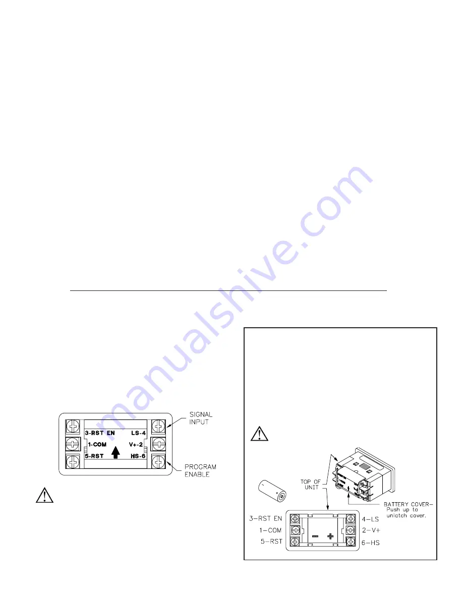
WIRING CONNECTIONS
The electrical connections are made via screw-clamp terminals located on
the back of the unit. All conductors should meet voltage and current ratings for
each terminal. Also, cabling should conform to appropriate standards of good
installation, local codes and regulations. It is recommended that power supplied
to the unit be protected by a fuse or circuit breaker. When wiring the unit, use
the battery cover to identify the wire position with the proper function. Strip the
wire, leaving approximately 1/4" bare wire exposed (stranded wires should be
tinned with solder). Insert the wire under the screw-clamp and tighten down the
screw until the wire is clamped in tightly. Each terminal can accept up to two
#14 AWG wires.
WARNING
: Lithium battery may explode if incinerated.
BATTERY INSTALLATION
1. Remove all power to the unit before removing battery cover.
2. To remove the battery cover, push upward in the direction of the arrow on
the rear cover (See drawing below), until the cover unlatches. Pull the
cover straight out from unit to fully remove.
3. Remove old battery* and replace it with an RLC battery (BNL10000).
Observe proper polarity when replacing the battery as shown in the
drawing.
4. Replace the cover. The battery cover is keyed so that it cannot be placed
upside down. The arrow on the rear of the cover should point toward the
top of the CUB7P when properly installed.
* - Dispose of properly.
WARNING
: Lithium battery may explode if incinerated.


