background image

Emergency opening of the door (RED)

7

BAL_SYS20_RED_EN_2V2_REC_102-020110693 

20/ 27


Emergency opening of the door (RED) 


Emergency opening with current supply 

By activating the emergency opening switch (optional), which must be placed beside the installation, 

the door will open as long as the operating mode Locked has not been selected. In this operating 

mode the door will remain locked. 

To re-start the installation, the emergency opening switch must be reset by hand, either through a ro-

tation or a pulling (different procedures depending on the version of the switch). 


Emergency opening in case of power failure with auxiliary battery (RED) 

  ▪  Emergency opening in case of power failure takes place via an auxiliary battery, which triggers a 

single opening of the door (except if function Locked has been selected). 

  ▪  Unlocking the door is still possible with the key-operated contact/switch (optional). 


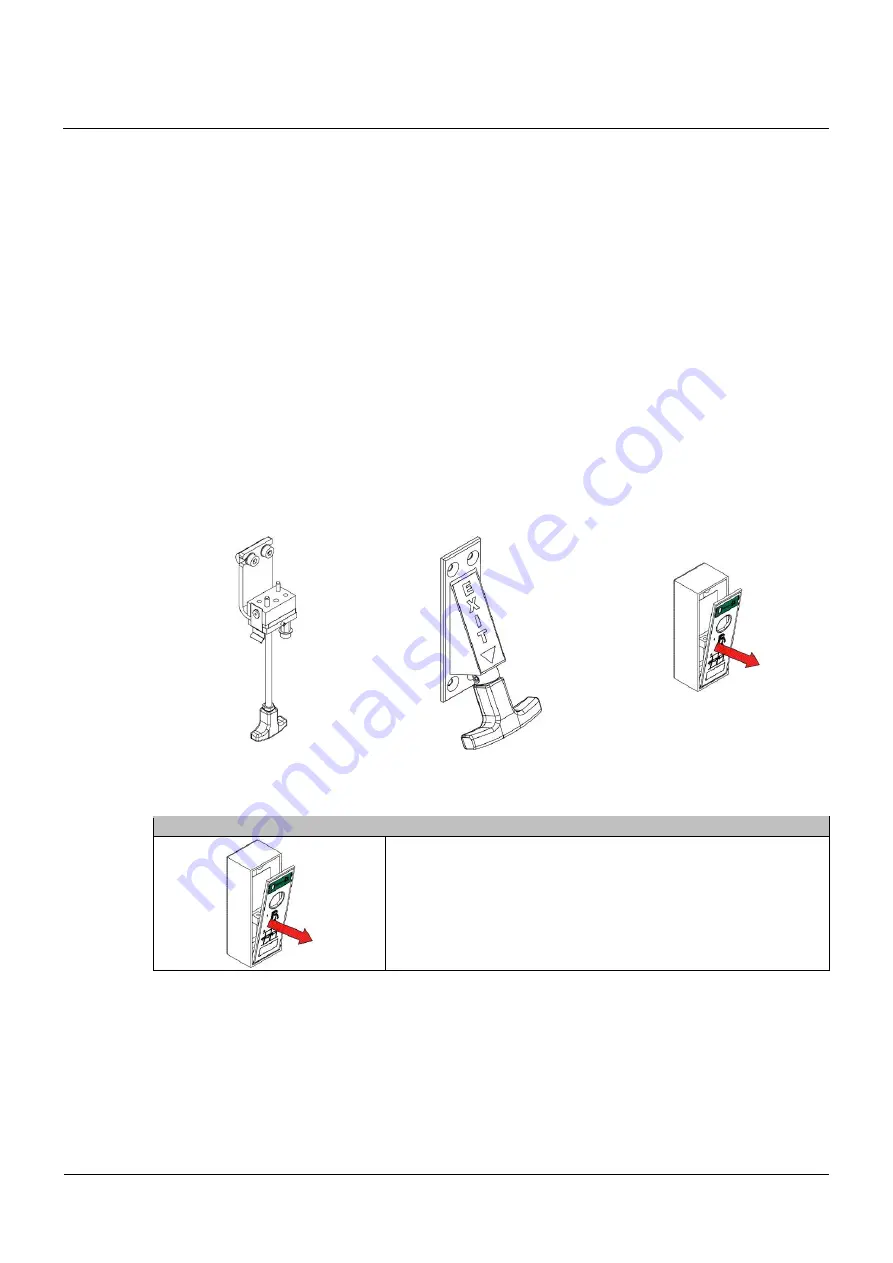
Emergency operating using Bowden cable (Option) 

This device, available in several versions, is mounted inside and/or outside and allows the unlocking 

of the door, according to the procedure below. 


Available versions 

The available versions are illustrated below. They are basically identical in their function. 


102-020808512 

102-020808757 

102-014102000 


Procedure for an emergency opening 


Emergency opening 


▪ Open the unlocking flap

  ▪  Pulling the unlocking flap downwards unlocks the door 

  ▪  Display on the BDE-D 

→ Error No. 31 / Emergency stop 

  ▪  The door can be slid open by hand 


7.1 

7.2 

7.3 

7.3.1 

7.3.2 

Summary of Contents for system 20 RED Series

Page 1: ...User manual record system 20 RED automatic door systems this is record Translation of the original manual ...

Page 2: ... of safety devices 8 1 7 Storage of the manual 8 2 General information 9 2 1 Document identification 9 2 2 Application range STA TSA 20RED 22RED 9 2 3 Target groups User 9 2 4 Door care 9 2 5 Maintenance and regular inspection 10 2 6 Operator duties 10 3 General technical data 12 3 1 Door opening speed 12 3 2 Power supply data 12 4 Operating instructions RED 13 4 1 Selection of operating modes RED...

Page 3: ...ure with auxiliary battery RED 20 7 3 Emergency operating using Bowden cable Option 20 7 3 1 Available versions 20 7 3 2 Procedure for an emergency opening 20 7 3 3 Closing and locking the door 21 8 Behaviour in event of faults 22 8 1 Display on the control unit 22 8 2 Possible troubleshooting 22 8 3 Resetting the control module 22 8 4 Control unit BDE D does not react 23 9 Functions and safety ch...

Page 4: ...S20_RED_EN_2V2_REC_102 020110693 4 27 Table of revisions D Document identification New chapter 9 S Safety Instructions and Regulations Chapter Sequence Changed 5 U Use of the device Note according to IEC 60335 1 2010 changed 6 ...

Page 5: ...le free operation of the system IMPORTANT Important details which must be read for proper function of the system CAUTION Against a potential hazardous situation that can lead to minor personal injury and property damage WARNING Against a latent hazardous situation that can lead to severe injuries or death and cause substantial property damage DANGER Against an imminent hazardous situation that can...

Page 6: ...g remote controls IMPORTANT When using motion detectors make sure that no moving objects such as flags plants etc enter the detection areas of the motion detectors IMPORTANT In order to avoid malfunctions the system must NOT be disconnected from the mains overnight IMPORTANT If malfunctions that endanger the safety of individuals occur the system must be turned off It may not be turned back on unt...

Page 7: ...n the product If necessary the country specific regulations have to be adhered to Reconstructions and changes to the product Unauthorized modifications to the installation will release the manufacturer from all liability for any re sulting damage State of technology This system was developed using state of the art technology and officially recognized technical safety regulations The system dependi...

Page 8: ...ervation of the operating conditions specified by the manufac turer in addition to regular care maintenance and repair Interventions in or alterations to the installation performed by non authorized maintenance technicians exclude the manufacturer s liability for consequential damages Control of safety devices Beside the maintenance carried out at regular intervals by a service technician or autho...

Page 9: ...It forms the basis of fault free working and gives instructions for the procedures to follow for rectifying any faults that may occur Extracts of this document can also be made accessible to persons entrusted with the day to day operation of the system The operating entity of the system must read this operating manual before commissioning the system and follow the safety instructions It is recomme...

Page 10: ...epartment in your region IMPORTANT A listing of recommended spare parts is supplied in the annex and is also availa ble on request at your service department Operator duties According to principles for inspecting automatic door systems in particular according to case law of safety obligations automatic door systems must be inspected by a qualified technician before com missioning and thereafter ac...

Page 11: ... 2 per year or accord ing to country specific directives and regula tions Yes Regular testing of fire doors Technical expert 1 per year or accord ing to country specific directives and regula tions Yes Regular functional test ing of lock for holding door open Operator 1 per year or accord ing to country specific directives and regula tions No Regular testing of lock for holding door open Technical...

Page 12: ... weight per wing 125 kg Noise emission 45 dB Protection class IP20 Door opening speed Door opening speed for max 75 of authorized door weight D STA D TSA 0 7 m 1 sec E STA E TSA 0 7m 1 5 sec Power supply data Product line 20 Product line 21 22 Standard DUO RED Standard RED Standard Mains voltage 100 240 VAC 100 240 VAC 230 VAC 100 240 VAC 230 VAC Rated power 90 W 90 W 85 W 90 W 120 W Fuse protecti...

Page 13: ... authorized person responsible for the key after this one has made sure that nobody else is on the premises Locking via external clock timer or control system is not allowed Key Operating mode Symbol Function Automatic Door opens unhindered from inside and outside Maximum opening width summer open ing Continuously open Door remains open until other operating mode is selected One Way Door opens onl...

Page 14: ...pedestrian automatic doors used as emergency exits so that they may not be inadvertently locked when the building is in use If a locked mode of operation is available the mode of operation must be protected e g by an ac cess code or a key so that changes can only be made by authorized personnel It is the responsibility of the operator of the pedestrian automatic door used as an emergency exit to l...

Page 15: ...he building is in use If a locked mode of operation is available the mode of operation must be protected e g by an ac cess code or a key so that changes can only be made by authorized personnel It is the responsibility of the operator of the pedestrian automatic door used as an emergency exit to lock the control panel into automatic position when the facility is being used The control panel BDE D ...

Page 16: ...From Locked to another one From One Way to another one However at least every 24 hours except in operating mode Locked as well as after a reboot of the STM control unit NOTICE After an incorrect self test the door opens and remains in the open position An alarm is released displayed on the BDE D Please inform your local service center Resetting the alarm An alarm can be activated for the following...

Page 17: ...pull near the hinges it will assist the opening of the casing Swivel out the red holding bar in order to keep the casing in open position As a precaution remove the plug from the socket The socket is located under the casing Besides unscrew both accumulator storage battery fuses The accumulator is located under the casing The locking system is provided with an un locking lever Turn the lever clock...

Page 18: ...ice is provided Inform service point Telephone number displayed on BDE D NOTICE If the door still cannot be operated and locked by hand please follow the steps described below Step 2 If the attempts to close and lock the door manually described under step 1 have remained unsuc cessful it indicates severe failure Please proceed as follows Set the door on Continuously open with the control unit Open...

Page 19: ...der the casing Slide the door by hand into the closed posi tion Turn the unlocking lever clockwise and hold it in this position so that the door can close completely The door will lock as soon as you release the lever Manually check that the door is properly locked Leaving the building in only possible through a second exit Inform service point Telephone number displayed on BDE D ...

Page 20: ...mergency opening in case of power failure takes place via an auxiliary battery which triggers a single opening of the door except if function Locked has been selected Unlocking the door is still possible with the key operated contact switch optional Emergency operating using Bowden cable Option This device available in several versions is mounted inside and or outside and allows the unlocking of t...

Page 21: ...ate the emergency opening This causes the locking device to be unlocked Slide the door manually into the closed position Keep the door leafs in the closed position Close the unlocking flap The door is now locked Check manually if the door is really locked NOTICE Same procedure for the other operating elements 7 3 3 ...

Page 22: ... This information provides the tech nician with important information s for troubleshooting If several status messages are active at the same time they are numbered e g error 1 2 Pressing the E button permits to navigate from one error message to the next one Example Which information Procedure How displayed Example Status text and number It is automatically displayed on the BDE D Software Version...

Page 23: ... or if no message appears on the dis play a reset of the control panel could eliminate the problem Proceed as follows RESET HARDWARE BDE D Press E key 12 seconds Display without any message Connecting to control unit Connection has been established example After resetting the control panel is again operational If this is not the case please inform our service center 8 4 ...

Page 24: ...mission are cleaned and adjusted Rel evant fixing screws are controlled and retightened if necessary Then functional testing is carried out for switching devices drives control units force or energy stor ing devices or command controllers The safety devices are adjusted and all the motion sequences including the final points are set A test run with final overall control of the door system is execu...

Page 25: ...revent the door from closing Therefore en sure that the indoor air is de humidified or wipe the exter nal sensor dry if necessary The sensor must cover the entire passage width The door is opened early and at an adequate speed to al low an unimpeded passage Door wings side parts Check the condition of the panes Check the condition of the gaskets profiles No damaged panes No torn out gaskets energy...

Page 26: ...m dirt cigarette butts etc The door leaf must be properly guided The movement of the door must not be obstructed by dirt Drive guard cover Check the fastening of the drive guard cover It must be completely closed and reliably engage in the hinges Protective wing optional de pending on national regulations Check the mechanical condi tion of the protective wing In particular check the clos ing mecha...

Page 27: ...If wear is detected Carriage Track Rubber damping profile If wear is detected Belt clamp If wear is detected Hinge plastic for cladding height 200 mm If wear is detected Locking device VRR If wear is detected Motor If wear is detected Leaf central seal If wear is detected Lateral sealing profile If wear is detected Floor guide rail If wear is detected Light barrier If wear is detected Control Brea...

Page 28: ... Annexe 2 Technology Drive Batley Wf17 6ER UK Southern Office 17 Invincible Road Farnborough Gu14 7QU UK tel 44 1698 376411 fax 44 1698 376422 record UK limited info recorduk co uk www recorduk co uk agtatec ltd Allmendstrasse 24 8320 Fehraltorf Switzerland tel 41 44 954 91 91 e mail record global export export record global www record global agtatec ltd Allmendstrasse 24 8320 Fehraltorf Switzerla...

Reviews: