31
U=0
No volt release switch
1
2
3
4
L
N
E
Blue
Brown
Gr
een / Y
ellow
Single phase
induction motor
Earth screwed to frame
L
N
E
12. Electrical Connection & Wiring Diagram
Machines supplied for use in the UK are fitted with a 3 pin plug conforming
to BS1363, fitted with a fuse conforming to BS1362 and appropriate to the
current rating of the machine.
Machines supplied for use in other countries within the European Union are
fitted with a 2 pin Schuko plug conforming to CEE 7/7.
Machines supplied for use in Australia & New Zealand are fitted with a 3 pin
plug conforming to AS/NZS3112.
In all cases, if the original plug or connector has to be replaced for any
reason, the wires within the mains power cable are colour coded as follows:
230 V (Single Phase)
Brown:
Live (L)
Blue:
Neutral (N)
Green and Yellow: Earth (E)
The wire coloured brown must always be connected to the terminal marked
‘L’ or coloured red.
The wire coloured blue must always be connected to the terminal marked ‘N’
or coloured black.
The wire coloured green and yellow must always be connected to the
terminal marked ‘E’ or with the earth symbol:
or coloured green / green and yellow.
It is important that the machine is effectively earthed. Some machines will be
clearly marked with the double insulated logo:
In this case there will not be an earth wire within the circuit.
In the case of the BS1363 plug for use in the UK, always ensure that it is
fitted with a fuse conforming to BS1362 appropriate to the rating of the
machine. If replacing the original fuse, always fit a fuse of equivalent rating
to the original. Never fit a fuse of a higher rating than the original. Never
modify the fuse or fuse holder to accept fuses of a different type or size.
Where the current rating of the machine exceeds 13 A at 230 V, or if the
machine is designated for use on a 400 V 3 phase supply a connector
conforming to BS4343 (CEE17 / IEC60309) will be used.
230 V machines will be fitted with a blue 3 pin connector. The wiring for this
type of this connector will be the same as shown above.
400 V, 3 phase machines will be fitted with a red 4 or 5 pin connector. The
wiring for this type of connector is as shown below:
400 V (3 phase)
Brown:
Live (L1)
Black:
Live (L2)
Grey:
Live (L 3)
Blue:
Neutral (N)
Green and Yellow: Earth (E)
The wire coloured brown must always be connected to the terminal
marked ‘L1’.
The wire coloured black must always be fitted to the terminal
marked ‘L2’.
The wire coloured grey must always be connected to the terminal
marked ‘L3’.
The wire coloured blue must always be connected to the terminal
marked ‘N’ or coloured black.
The wire coloured green and yellow must always be connected to the
terminal marked ‘E’ or with the earth symbol
If in doubt about the connection of the electrical supply, always consult a
qualified electrician.
Summary of Contents for BS300E Premium
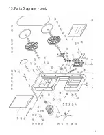
Page 33: ...33 13 Parts Diagrams cont ...
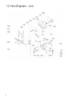
Page 34: ...34 13 Parts Diagrams cont ...
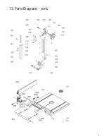
Page 35: ...35 13 Parts Diagrams cont ...

