background image

GR

GR

GR

GR

REC Peak Energy Series Installation Manual - UL 1703

Ref: NE-06-03-M 

Rev M - 03.2014

7

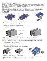
fig. 7:  Drainage holes

v)  Drainage holes

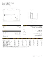
There are eight drainage holes, 0.47 x 0.30 in (12 x 7.5 mm) in the panels frame, each spaced 2.2 in (55 mm) from the corner of the panel frame (fig. 

5).  This allows water caused by rain or snow melt to exit the frame easily and minimizes the damage caused by freezing and thawing.  ensure these 

holes are not covered by any part of the mounting structure.

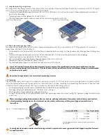
Part Name

Material

Specification

bolt

asTM f593 (stainless steel)

1/4” x 20 - 5/8”

flange Nut

asTM f594 (stainless steel)

1/4” x 20 

When using mounting holes, fixings must be fastened to 9 ft-lbs (12 Nm) of torque and installation must be according to fig. 6.

Install the above parts as shown in fig. 6.  Consult the Unirac Code Compliant Installation Manual for further details where necessary.  

For areas where discrepancy may exist, this installation manual shall take precedence.

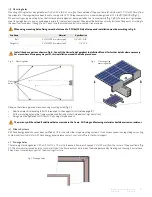
iii) mounting holes

Mounting utilizing the four elongated holes (0.26 x 0.43 in (6.6 x 11 mm)) on the underside of the panel frame (at a distance of 17.72 in (450 mm) from 

the midpoint of the long side) have been found to comply with ul 1703 requirements for a maximum design load of 75.2 lbs/ft² (3600 Pa) (fig. 5).
when mounting using mounting holes, the frame and panel edge must be supported by two transverse rails (fig. 1, p 8), 

of aluminium or galvanized 

steel to avoid galvanic corrosion and be appropriate for the local environment.  These must be

 held in position by bolts and flange nuts according to 

the specifications below.  if bought in a kit, do not use the washers and bottom mounted clips provided:

observe the following procedures when using mounting holes (fig. 5):

• 

additional electrical bonding to earth is required for the support structure (see page 12).

• 

all four mounting holes in the frame must be used (for long or short-sided mounting orientation).

• 

fixings must be tightened to 

9 ft-lbs (12 Nm)

 using a torque wrench.

The warranty will be voided if additional holes are made in the frame.  All fixing and fastening materials should be corrosion resistant.

Mounting

holes

fig. 5:  Mounting holes

fig. 6:  Mounting using  

mounting holes

iv) slide-in systems

reC Peak energy panels have not been certified by ul for use with slide-in type mounting systems.  if you have any questions regarding a mounting 

system and its suitability for reC Peak energy panels, please contact your local office for technical support.

38

GR

GR

GR

GR

28

1665±2,5

900

382,5

950

991±2,5

17

45

11±0,2

6,6±0,2

20,5±0,5

Summary of Contents for REC235 Series

Page 1: ...InstallatIon manual rec Peak energy series For the installation of panels certified according to UL 1703...

Page 2: ...ireMeNTs 4 meCHanICal InstallatIon 5 fire guiDeliNes 5 orieNTaTioN 5 eNviroNMeNTal faCTors 5 PaNel HaNDliNg 5 mountInG tHe panels 6 PaNel iNsTallaTioN 6 i rail sPeCifiCaTioNs 6 ii ClaMP sPeCifiCaTioN...

Page 3: ...w icons which highlight important information or notes Indicates potential for damage to the array or property or personal safety Indicates important notes on best practice to help with the installati...

Page 4: ...requirements of the NeC the values of isC andvoC marked on the panels must be multiplied by a factor of 1 25 when determining component voltage ratings conductor ampacities overcurrent device ratings...

Page 5: ...th local authorities for applicable regulations concerning setbacks or other placement restrictions that may apply for roof mounted arrays The use of DC ground fault interrupters is recommended This m...

Page 6: ...rails fig 2 Thickness of walls for mechanical connections min 0 156 in 4 0 mm Thickness of walls exposed to buckling load min 0 08 in 2 0 mm Moment of inertia for profile area about x x min array moun...

Page 7: ...1703requirementsforamaximumdesignloadof75 2lbs ft 3600Pa fig 5 when mounting using mounting holes the frame and panel edge must be supported by two transverse rails fig 1 p 8 of aluminium or galvanize...

Page 8: ...reC Peak energy panels utilizing clamps on the two long sides of the panel have been found to be in compliance with ul 1703 require ments for a maximum design load of 75 2 lbs ft 3600 Pa fig 8 Clamps...

Page 9: ...ical integrity of the cables is intact bonding points to ground are tight secure and free from corrosion which could break the continuity between the panels and ground ReCyClInG reC has made every eff...

Page 10: ...normal operation This will help to shield the panel from direct water spray InstallatIon InstRuCtIon i system installation all cables used for the installation must have sufficient length and slack t...

Page 11: ...of the indicated values of isC voC and PMPP under standard test conditions sTC values at sTC airmass aM 1 5 irradiance 1000 w m cell temperature 25 C 77 f at low irradiance of 200 w m aM 1 5 and cell...

Page 12: ...2013 i 2 addition of low watt classes 214 230wp for ul records 04 2013 i 3 update of tightening torque for clamping and mounting holes 06 2013 i 4 update of torque rating for long side clamping and m...

Page 13: ...RECSoLaRPtE Ltd 20tuasSouthavenue14 Singapore637312 Singapore tel 6564959228 Mail post recgroup com www recgroup com...

Reviews: