REC Peak Energy Series Installation Manual - UL 1703
Ref: NE-06-03-M
Rev M - 03.2014
8
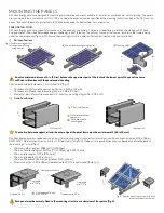
vii) short side mounting using clamps
Mounting utilizing clamps on the two short sides of the panel have been found to be in compliance with ul 1703 requirements for a maximum
design load of 33.4 lbs/ft² (1600 Pa) (fig. 9).
•
fix the panels so that the lower short side of the frame is supported by the mounting structure (to reduce risk of damages due to sliding snow
load).
•
Clamps must be secured between a distance of 4.9 and 9.8 inches (125 – 250 mm) from the panel corner to the clamp edge.
•
Tightening torque must be tightened to 16 ft-lbs (21.7 Nm).
•
The minimum distance between the end clamp and the end of the rail is 1 in (25 mm).
•
Mechanical load must not exceed 33.4 lbs/ft (1600 Pa).
•
The overlap between support rail and frame must be a minimum of 1/4 in (6 mm).
In areas of snow build-up, panels can be subjected to forces in excess of the stated limit even when snow depth does not appear
extreme, causing damage to the framework. If the installation is likely to be affected, further suitable panel support is recommended
on the lower row of panels.
Ensure the drainage holes are not covered by the mounting structure.
Where common grounding hardware (nuts, bolts, star washers, split-ring lock washers, flat washers and the like) are used to attach
a listed grounding/bonding device, the attachment must be made in conformance with the grounding device manufacturer’s
instructions.
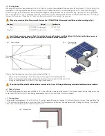
vi) long side mounting using clamps
Mounting of reC Peak energy panels utilizing clamps on the two long sides of the panel have been found to be in compliance with ul 1703 require-
ments for a maximum design load of 75.2 lbs/ft² (3600 Pa) (fig. 8).
•
Clamps must be secured between a distance of
8.2 in to 16.4 in (208 mm - 416 mm)
from the corner of the panel (measured from the mid-
point) to the clamp edge.
•
Tightening torque must be tightened to 9 ft-lbs (12 Nm).
•
The distance between the end clamp and the end of the rail must be minimum 1 in (25 mm).
fig. 8: long side mounting
fig. 9: short side mounting
8.2”-
16.4”
1”
1”
4.9”-
9.8”
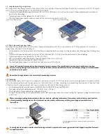
viii) Grounding
a panel with exposed conductive parts is considered to be in compliance with ul 1703 only when it is electrically grounded in accordance with the
instructions presented below and the requirements of the National electrical Code. grounding is achieved through securement to the panel frame
of the following ul listed grounding Clips / lugs in combination with the reC Peak energy panel(s).
•
suitable grounding lugs must be used: listed (kDer) ilsCo, gbl-4DbT (tin plated) (e34440).
•
grounding cable size should be between 4 - 14 awg (2.1 mm²
- 21.2mm²).
•
attach grounds to the grounding holes in the panel frames.
•
fix lug to the frame using a star washer (#10) and lock nut (#10), ensuring a conductive connection (fig. 10). Tighten according to manufacturer’s
instructions.
fig. 10: recommended grounding
Cross section [AWG]
Type Torque [in-lbs]
4 - 6
stranded
35
8
stranded
25
10 - 14
stranded / solid
2.8
To avoid galvanic corrosion, stainless steel fastening materials are preferred, however galvanized or hot dipped zinc plated fasteners
are equally suitable.
grounding
cable
star washer
grounding lug dimensions and wire fastening torque for
gbl-4DbT

