GPS Vehicle Tracker User Manual
Page 16
ON OFF
(BLACK) Ground
(RED) +12VDC
(Yellow)
White
Yellow
(White)
High-Voltage Ingiton winding
Green
Green
Relay
P1
P2
P1
P2
Engine Ignition Loop
Fuel Pump
'
s Power Supply Loop
D
P1
P2
Fuel Pump
'
s Motor
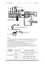
Notes:
(1). The relay
'
s control output (2 green lines, no polarity) has 2 kinds of connections. It can be
used to cut off the engine ignition loop or the fuel pump
'
s power supply loop. It is suggested to
control the fuel pump.
(2). Please turn the switch to ON position. It is the switch of the inside backup battery.
(3). The 12-pins wiring harness are optional components.
(4). The SOS button and LED are already connected in the 12-pins wiring harness.
(5). The shock sensor is connected to the 12-pins wiring harness
(6). The Orange line in 12-pins connector can be connected with positive of alarm siren or car
lamp. No matter in arming or disarming status, once it d12VDC signal for at least 8
seconds, it will send out alert.
1
2
3
4
+
Car Battery
5
6
11
12
3
4
9
10
1
2
7
8
ACC ON
Blue
LED
Original alarm siren
Door Switch
Red Orange
SOS Switch
yellow Black
GND
GND
GND
(Null)
+12V
Arm/Disarm Signal line.
+12VDC voltage: Disarm system
0 VDC (Ground): Arm System
4P & 12P
Connector
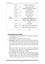
Color
No.
Function & connection
Red
1
Positive input from car battery
(
DC12V
)
Black
2
Negative input
(
GND
)
white
3
Relay
’
s positive control output
4-PIN connector
yellow
4
Relay
’
s negative control output


