Manual (Translated)
FirePro V2 Control Unit
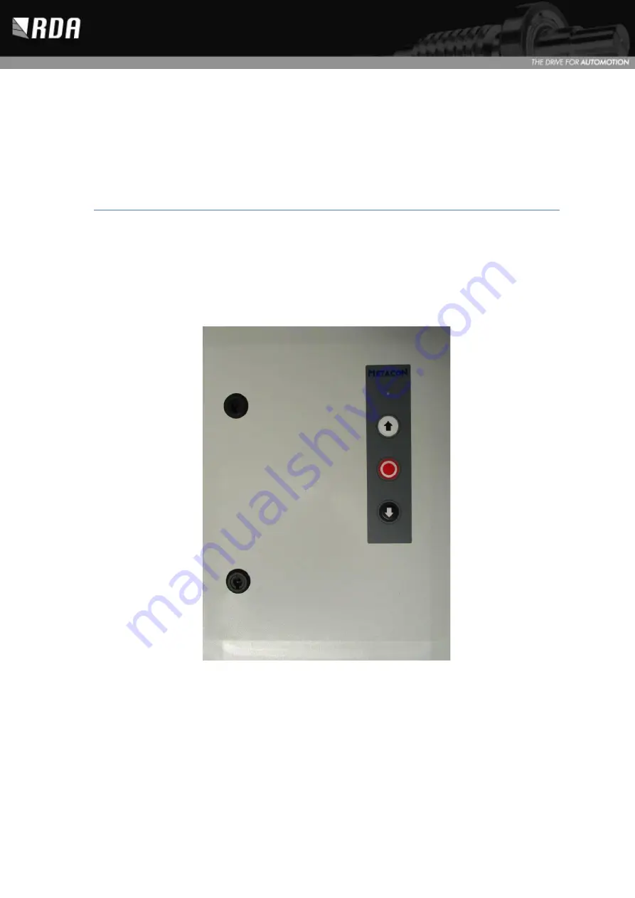
Door control for FS drives:
EN
FirePro V2 Control Hardware version V2. 3 Software version V4.1 Publication Date: 02/12/2021
Page 1: ...Manual Translated FirePro V2 Control Unit Door control for FS drives EN FirePro V2 Control Hardware version V2 3 Software version V4 1 Publication Date 02 12 2021...
Page 2: ...Door control FireProV2 Manual Please keep this manual with attachments carefully 1...
Page 3: ...4 9 4 Mechanical End Switches 14 9 5 Digital limit switches 15 9 6 Roll off cable break slack cable protection 15 9 7 UP Stop down operation 16 9 8 Photocell 16 9 9 Light curtain 16 9 10 Connecting LI...
Page 4: ...12 Notifications 29 10 13 Maintenance counter 30 11 Menu 31 11 1 Parameter settings 0 31 11 2 Parameter settings 1 33 11 3 Parameter settings 2 34 11 4 Parameter settings 3 35 11 5 Parameter settings...
Page 5: ...ufacturer is not responsible for damage that has occurred due to external components or non compliance with these instructions Modifications are only permitted in accordance with the manufacturer If m...
Page 6: ...Door control FireProV2 Manual Please keep this manual with attachments carefully 5 3 Control Print Overview...
Page 7: ...Door control FireProV2 Manual Please keep this manual with attachments carefully 6 4 Schedule with NES motor...
Page 8: ...Door control FireProV2 Manual Please keep this manual with attachments carefully 7 5 Schedule with DES motor...
Page 9: ...t 100mA Battery Voltage 12v LxWxH 151x51x94mm Brand CSB Battery Type UPS123607 Weight 1 97 kg Technology AGM Relay outputs Potential free switch contacts Maximum load 230VAC resistive last 1A inductiv...
Page 10: ...on A Stop with a set time can optionally be made at a desired position during fire alarm smoke detection or low battery voltage This can only be used with CAM switches when the overclose function is n...
Page 11: ...mediately when the mains supply is still present In the case of smoke detection the door shutter can no longer be opened if it is completely closed unless it is chosen to partially open the door 7 8 M...
Page 12: ...e following applies Connect the control unit to a fixed power supply line and fuse the power supply as indicated earlier To interrupt the power supply a multi pole switch must be mounted in the immedi...
Page 13: ...g circuit board 9 1 Power supply The power supply 3N 400VAC 1 230VAC or 3 230VAC is connected to X1 The diagram below lists the different schedules The earth PE is connected to X3 Connect the earth to...
Page 14: ...Connecting 230VAC voltage to power supply charger The output of the power supply charger is equipped with a stitch connector It can be plugged in at X16 see Fig 4 This ensures the power supply for th...
Page 15: ...ng the brake observe the polarity correctly The positive and negative may not be changed 3 Phase 400V 3 Phase 230V Only with GFA Connect Motor in star Connect Motor in Triangle FS 15 WS drive Figuur 5...
Page 16: ...ing parameter 9 5 setting 1 Then make the installation power less and switch the encoder for an encoder of another type 9 6 Roll off cable break slack cable protection Connection X6 is for the NC cont...
Page 17: ...X10 There is also a 24VDC power supply on X10 for the power supply of a photocell or any other accessories like e g A receiver In addition an entrance for the NC contact of the photocell is also prov...
Page 18: ...et Test function Transmitter Option 1 Black Siren output Test input X13 NC Siren Test 24V DC X13 C Siren Parameter 5 1 5 Test function light curtain Option 2 Black Alarm output Test input X13 NC Alarm...
Page 19: ...the light curtain also no longer automatically adjusts itself after this setting This is to prevent the light reflections from leading to unwanted reversing of the door Note This only works with a dis...
Page 20: ...lease note With light curtain LIGI 07 the door function is always activated Figure 1 connection schedule Transmitter Receiver Brown 10 30V DC X10 X10 Brown 10 30V DC X10 Blue 0V DC Blue 0V DC X10 Whit...
Page 21: ...nd connecting it to the 0 VDC GND Reset to factory defaults Connect the Sync white wires for at least 15 seconds and up to 25 seconds with the 24V DC Advice Remove after all the settings the power fro...
Page 22: ...the potential free NC Contact of the fire alarm or smoke detector can be connected to number 3 and 4 which is interrupted in case of fire calamity If this input is not used it must be connected with a...
Page 23: ...ry to check and be determined whether the door with electric actuator complies with the Guidelines EN 12445 and 12453 Locally applicable standards should also be to be maintained 9 17 Siren Alarm On X...
Page 24: ...shutter is cleared again After the reset command the door will only active after a set time parameter 4 5 In the meantime the door cannot be operated Only then will the door roller shutter function no...
Page 25: ...p this manual with attachments carefully 24 Figure 17 input smoke detection and reset after smoke detection Figure 18 Potential free contact door roller shutter close to smoke detection Figure 19 conn...
Page 26: ...letely switched off Please Note The door closes the last piece without security This will allow the door roller shutter to close completely and not be ajar due to the underrun protection 10 2 Adjust l...
Page 27: ...nd position Random Pre end Open Close Position Position 10 3 Automatic or hold to run operation The door runs in hold to run open and close when the controller is set to factory settings If desired th...
Page 28: ...f the mains supply is still present waits for the time set to parameter 0 5 and then closes again If the mains supply is not present the door shutter stops and continue to close after the set time par...
Page 29: ...t drops to this position and will wait for a set time parameter 4 2 and then close further 10 8 RM Smoke detection with Reset function In the case of smoke the same as a fire alarm occurs Here are two...
Page 30: ...tion does not monitor the end positions direction of rotation and movement Make sure that the button is released in time 10 11Low battery voltage The level at which a notification should be given that...
Page 31: ...a maintenance counter can be activated with parameter 8 7 Parameter 8 5 can then set the number of openings per 1 000 before a maintenance notification is given When this counter reaches zero the Led...
Page 32: ...and confirm the change press stop OK briefly To exit the menu go to parameter 0 0 and press stop OK briefly 11 1 Parameter settings 0 Parameter Description Settings 0 0 Exit Menu Exit the menu by pre...
Page 33: ...ter set time parameter 0 5 6 activate safety edge and photo cell Stop when Photo Cell is activated and continue closing after set time parameter 0 5 7 Enable safety edge and photocell If power supply...
Page 34: ...t m 9 1 5 Adjust pre end position close Adjust pre end position upwards or down 0 t m 9 1 6 Partial opening for fire escape Parameter 1 7 must be set 1 Switched off door opens completely in case of fi...
Page 35: ...l operation 0 Time restarts at photocell interruption 0 1 After interruption photo cell the door will close after 3 seconds regardless of the time left 2 5 Number of re openings at automatic closing a...
Page 36: ...n pressing and immediately close again after releasing 3 4 BM function after BMC has been active 0 t m 140 seconds 0 sec 3 5 Number of attempts activation safety edge or photocell in case of fire 0 t...
Page 37: ...NES 1 1 Close completely 2 Partial opening For partial opening the door is sent to position of S6 Parameter 3 1 may not be set to 2 DES 1 Close completely 2 Partial opening For partial opening the do...
Page 38: ...ctive 3 Photo cell notification and safety edge interrupted defective 4 Test function light curtain 5 3 Function alarm output 1 Switches when the door closes in case of calamity 1 2 Test function ligh...
Page 39: ...eans of the key switch on the cover the point on the right side of the display will be lid Key switch activated 12 1 E Status notifications Notification Description E 1 1 Operation open active E 1 2 O...
Page 40: ...bridge on this connection F 2 0 No safety edge present This notification is given when it is chosen to automatically detect the safety edge If the safety edge is not detected during the start up of t...
Page 41: ...the resistance of connector X11 GND and 1K2 8K2 input is still 1 2KOhm Check the spiral cord for any cable breaks Check pre limit switch is correctly and ensure that the safety edge rubber is pressed...
Page 42: ...the digital limit switch of the motor if it is defective F 5 6 Door movement error Check the door mechanically F 5 7 Error in direction of rotation Direction of rotation has been changed after enteri...
Page 43: ...monitor the end positions direction of rotation and movement Do not allow the door to move further then partial opening with a correct direction of rotation F 1 3 5 5 DES not recognized Press the midd...
Page 44: ...ironments EN 61000 6 3 Electromagnetic compatibility EMC part 6 3 general standards interference emission for household commercial and light industrial environments On the reasoned request of the nati...
Page 45: ...Door control FireProV2 Manual Please keep this manual with attachments carefully 44...
Page 46: ...T 31 0 416 23 50 39 E service rda bv nl www rda bv nl This symbol crossed out dustbin means that the end user has to take care of the household waste for the disposal of this product The purpose of th...