background image

24

Tour of the Receiver

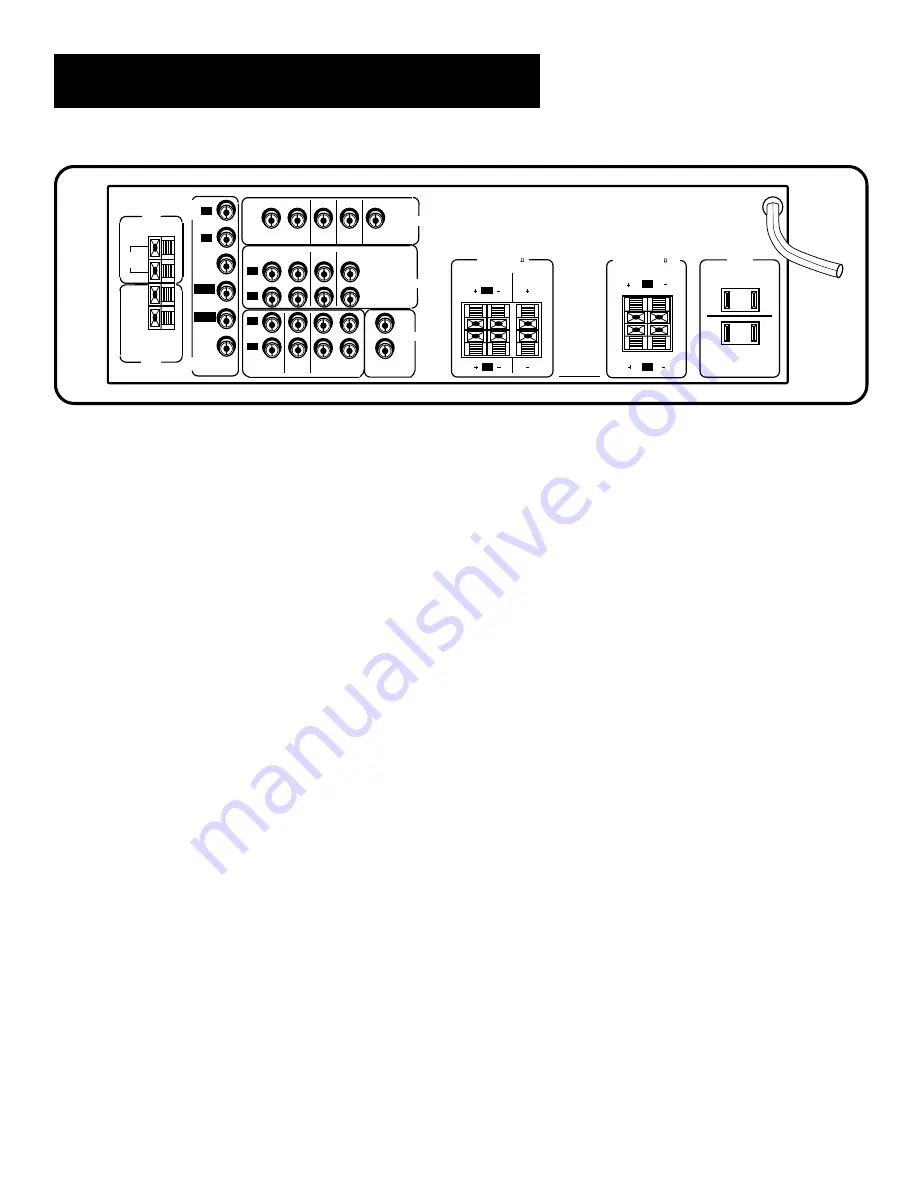
back panel

AUDIO Connections  

Provides audio connections for

components such as a VCR, TV, CD player, laserdisc player, DVD
player or tape player.

IN

  Provides audio input from another component.

OUT

  Sends audio output to another component, such as a

minidisc, tape player or VCR.  Sends a signal to the

subwoofer.

VIDEO Connections

  Provides video connections for the video

portion of another component such as a VCR, TV, laserdisc player,
DVD player or satellite receiver.

IN  

Provides video input from another video component.

OUT

  Sends video output to another video component

such as a VCR.

Monitor Out

  Sends video output to the TV.

SPEAKERS

  Provides connection to the speakers.

SURROUND SPEAKERS

  Provides connection for the Surround

Sound Speakers.

AC Outlets  

One switched AC outlet and one unswitched AC

outlet provide A/C power outlets for other components.

FM ANT

  Provides connection for an FM antenna.

AM ANT

  Provides connection for an AM antenna..

REAR

120V 60Hz

SWITCHED 180W, 1.5A MAX

UNSWITCHED 180W, 1.5A MAX

CENTER

VCR 

(MONO)

1

2

SUB WOOFER
OUT

AUDIO

L

R

MAIN

L

R

FRONT SPEAKERS (8   )

AC OUTLETS

SURROUND SPEAKERS (4    MIN.)

IN                  OUT

DVD/

LD

SAT

AUDIO

L

R

IN                  OUT

CD

TAPE/MD

TV

L

R

VCR SAT

IN                  OUT

VIDEO

DVD/

LD

MONITOR

OUT

DVD5.1

L

R

AM ANT

300

BAL

FM ANT

DVD

5.1

AUDIO

CENTER

L-SUR

SUB

WOOFER

REAR

R-SUR

Summary of Contents for RV-3798

Page 1: ...USER S GUIDE AUDIO VIDEO RECEIVER RV 3798 ...

Page 2: ...l injury Refer to the identification rating label located on the back panel of your product for its proper operating voltage FCC Regulations state that unauthorized changes or modifications to this equipment may void the user s authority to operate it WARNING To reduce fire or shock hazard do not expose this product to rain or moisture Caution To reduce the risk of electric shock match wide blade ...

Page 3: ...yer 32 Programming the Remote to Control an RCA DSS Receiver 33 Programming the Remote to Control a Satellite Receiver 33 Appendix A Connecting Your Receiver 35 Things to know before connecting the components 35 Using the Subwoofer Connections 36 Connecting a TV and VCR 37 Connecting an RCA DSS Receiver 38 Connecting a DVD Player 39 Connecting a Second VCR 40 Connecting a Camcorder or Video Camera...

Page 4: ...2 Table of Contents Appendix F Limited Warranty 51 Appendix G Equipment Specifications 52 Appendix H Preset Station List Form 54 Index 55 ...

Page 5: ... s manual shows you how to use your audio receiver for the first time The next three sections tell you about using the receiver s controls and programming the remote Use the last sections of the manual to connect your receiver to other components and as a general reference If you have a specific question refer to the table of contents or the index PLEASE READ THE NOTES IN THE TEXT The engineers an...

Page 6: ...e Appendix A Connecting the Receiver For three suggestions on placing your speakers for the best sound see Appendix B Speaker Placement Page 47 TV Only Do not plug your TV or VCR into the switched outlet on the back of the receiver You will need 1 paired red white stereo cable 1 single yellow video cable or 1 stereo A V cable 1 coaxial cable Connect the cables as shown to the right VCR MONO 1 2 SU...

Page 7: ...ert the four AAA batteries matching the and ends of each battery with the symbols in the compartment 3 Replace the cover Step 4 Plug in the receiver Before you plug in the receiver connect the other components and speakers Plug the power cord into the wall outlet matching the wide blade of the plug with the wide slot in the outlet Be sure to insert the plug completely Step 5 Turn on the receiver P...

Page 8: ...6 ...

Page 9: ...tion refer to Chapter 3 Tour of the Receiver 2 3 4 Programming the Remote First Things First Operating the Receiver Tour of the receiver Important In order to safeguard your hearing turn the volume down before turning on your receiver Unless otherwise specified the buttons mentioned in this chapter are on the remote control ...

Page 10: ...ay Beginning at its current frequency the tuner finds and stops on the next station whose frequency is strong enough to be received To continue the search press INPUT SEEK again Storing Stations in Memory You can store up to 30 AM and FM stations These stations can be stored in random order Use the convenient Preset Stations List in this guide to note the name and location of the stations you have...

Page 11: ...nning Use P SCAN Preset Scan on the receiver s front panel to review the preset stations stored in the tuner s memory Press P SCAN PRESET and the station s location in memory appear in the display The tuner automatically scans all preset stations in order pausing at each one for approximately 4 seconds When the tuner reaches the station you want press P SCAN to stop the scanning If the scan is not...

Page 12: ...the left main channel 2 Press REAR CENTER again and adjust the center main channel 3 Press REAR CENTER again and adjust the left rear channel 4 Press REAR CENTER two more times and adjust the right rear channel the center main channel must be passed through to adjust the right rear channel 5 Press REAR CENTER again to adjust the right main channel 6 Press TEST again to end the test 3 You will make...

Page 13: ...to watch on the large screen 6 Press SWAP AUDIO to swap the sound between the large picture and the small picture 7 To swap the video between the large picture and the small picture use the SWAP PIP button on the remote If you swap the TV picture to the PIP and the other video source to the large picture you may not be able to swap the audio To Change the Video Source and swap the audio If you wan...

Page 14: ...12 ...

Page 15: ...nnections This section describes the receiver s controls and connections including The front panel The front panel display The remote control The back panel 4Programming the Remote Operating the Receiver First Things First 3Tour of the Receiver ...

Page 16: ...r The signal intended for the center speaker is divided equally between the left and right main speakers Phantom mode is not available in 3 Stereo mode CENTER Selects the center speaker so you can adjust the volume level CD Selects the CD player input DELAY Lets you choose 15 20 or 30 milliseconds as the sound delay in the rear speaker to adjust the audio output for room size When listening the cl...

Page 17: ...Logic surround sound with Surround sound speakers and is suggested for video home theater TV and some music This is the recommended mode if you have all speakers Dolby 3 Stereo Turns on Dolby Pro Logic surround sound without Surround sound speakers and is suggested for video home theater TV and some music Hall Turns on Sound system without a center speaker and is suggested for classical music jazz...

Page 18: ...tation is selected MUTE The sound is muted The MUTE symbol blinks in the front panel display when the sound is muted PRESET The receiver is tuned to a preset station The PRESET symbol blinks in the front panel display when the receiver is scanning stays on when you are listening to a preset station and turns off when you manually tune the receiver SEEK The receiver is in seek mode and searching fo...

Page 19: ...OUND MODE or the selected CENTER MODE Tour of the Receiver Selected Center Mode mS PRO LOGIC Station Frequency Band STEREO MHz PRESET Selected Surround Mode mS Function Mode mS PRO LOGIC surround memory If you have entered different surround modes for different pieces of equipment the receiver saves each sourround mode independently The TV surround setting will always be the same as the satellite ...

Page 20: ...AM band and the FM band CTR MODE Changes the Center mode when using Dolby Pro Logic Surround or Dolby 3 Stereo surround modes Press once and the current mode appears Press again to change the mode DELAY CH CTRL Selects the amount of Surround Sound delay between the main and rear speakers Choose from 15 20 or 30 milliseconds Press once and the current setting appears Press again to change the setti...

Page 21: ...stations with signals of sufficient strength MENU SELECT Stores the selected station in the receiver s memory Number Buttons Let you enter numbers when needed REV Lets you manually move down the AM FM band TV Controls On some RCA TV models used to adjust menu controls On some RCA TV models used to adjust menu controls ANTENNA Changes the antenna input CHAN and CHAN Tunes the TV channel up and down...

Page 22: ...he main picture in the PIP window TV Turns on the TV and puts the remote in TV mode TV MENU Displays the TV s on screen menus VCR Controls CHAN and CHAN Tunes to the next or previous channel when watching TV through the VCR CLEAR Resets the tape counter and corrects entries when programming the menus FWD Fast forwards a tape Also searches forward while a tape is playing GO BACK DISC Returns to the...

Page 23: ...s you toggle through programmed playback standard playback and random playback POWER Turns the DVD player off REW Scans backward on the DVD STOP Stops the DVD SATELLITE Receiver Controls ANTENNA Toggles between antenna input and satellite receiver input CH and CH Tunes to the next or previous channel when watching TV through the satellite system Steps through the pages in the guide if in guide mod...

Page 24: ...U SELECT Programs the CD changer to play up to 32 tracks in any order you choose Number Buttons Let you enter numbers when needed PAUSE Pauses the CD PLAY Plays the CD RESET REP Repeats a track a CD or an entire program Press once to repeat the currently playing track twice for the CD or program and three times to turn the function off REV Moves backward through the CD one track at a time STOP Sto...

Page 25: ...isc FWD Scans forward on the laserdisc LD VCR2 For some laserdisc models if programmed turns on the laserdisc player and puts the remote in laserdisc mode Number Buttons Let you change to a specific chapter PAUSE Pauses the laserdisc PLAY Plays a laserdisc PLAYLIST For some laserdisc models if programmed programs to playback chapters on laserdisc in a certain order POWER Turns the laserdisc player...

Page 26: ...o output to another video component such as a VCR Monitor Out Sends video output to the TV SPEAKERS Provides connection to the speakers SURROUND SPEAKERS Provides connection for the Surround Sound Speakers AC Outlets One switched AC outlet and one unswitched AC outlet provide A C power outlets for other components FM ANT Provides connection for an FM antenna AM ANT Provides connection for an AM an...

Page 27: ...ith most other RCA GE and ProScan TVs and VCRs You however can program the remote to control most brands of remote controllable TVs VCRs cable boxes satellite receivers and audio equipment Programming the Remote Programming the Remote First Things First Operating the Receiver 3 Tour of the Receiver ...

Page 28: ...e Follow these steps to program your remote to control your TV 1 Turn on the TV 2 Look up your TV brand and code number s in the code list on the next page or on the code sheet packed with your remote 3 Press and hold the TV button on the remote 4 Enter the three digit code from the code list 5 Release the TV button then press POWER to see if the TV responds to the remote commands If not try press...

Page 29: ...Mathes 000 011 015 027 037 CXC 064 Daewoo 011 019 027 112 Daytron 011 027 Dimensia 000 Electrohome 006 011 014 027 038 061 068 Emerson 011 026 027 028 029 030 031 032 037 042 053 064 065 067 075 076 078 079 094 095 096 Envision 011 027 Fisher 017 021 039 041 Funai 064 GE 000 008 009 011 012 027 038 068 086 089 091 Goldstar 003 004 006 011 019 027 037 050 Hallmark 011 027 Hitachi 009 011 027 036 03...

Page 30: ...the code list on the next page or on the code sheet packed with your remote 3 Press and hold the VCR1 button on the remote 4 Enter the three digit code from the code list 5 Release the VCR button then press POWER to see if the VCR responds to the remote commands If not try pressing VCR then POWER 6 Repeat steps 3 through 5 using the next code listed for your VCR brand until the VCR responds to the...

Page 31: ...09 013 044 045 046 052 Colortyme 014 Craig 007 012 Curtis Mathes 000 007 008 014 015 044 046 053 064 067 Daewoo 013 045 052 076 dbx 014 016 Dimensia 000 Dynatech 015 Electrohome 027 Emerson 008 009 010 013 015 020 023 027 034 041 042 047 049 057 062 065 067 068 070 Fisher 002 012 018 019 043 048 058 Funai 015 GE 000 007 008 032 037 053 Goldstar 009 014 046 060 Harman Kardon 014 Hitachi 005 015 035...

Page 32: ...on then POWER again 6 Repeat steps 3 through 5 using the next code listed for the brand of your component until the component responds to the remote commands Programming the Remote This remote may not operate all models of the brands shown ads AMP 001 Aiwa CD 060 Akai AMP 002 008 Denon CD 057 Dynamic Bass AM FM 029 CD 025 TAPE 026 027 PHONO 028 Emerson CD 066 Fisher AMP 023 CD 067 Hitachi CD 063 J...

Page 33: ...hrough 5 using the next code listed for the brand of your cable box until the cable box responds to the remote commands This remote may not operate all models of the brands shown ABC 022 046 053 054 Anvision 007 008 Cablestar 007 008 Diamond 056 Eagle 007 008 Eastern International 002 General Instrument 046 GI 400 004 005 015 023 024 025 030 036 Hamlin 003 012 013 034 048 Hitachi 037 043 046 Jerro...

Page 34: ...te commands If it doesn t try pressing LD VCR2 then POWER again 6 Repeat steps 3 through 5 using the next code listed for your brand until the laserdisc player responds to the remote commands PROGRAMMING THE REMOTE TO CONTROL A DVD PLAYER The remote is preprogrammed to control a RCA DVD player A few of the remote buttons used with a DVD player are shown below You may want to experiment with other ...

Page 35: ...in the code list on the right 3 Press and hold the SAT CABLE button on the remote 4 Enter the three digit code from the code list 5 Release the SAT CABLE button then press POWER or CH or CH to see if the receiver responds to the remote commands If it doesn t try pressing SAT CABLE then POWER again 6 Repeat steps 3 through 5 using the next code listed for the brand of your receiver until the receiv...

Page 36: ...34 ...

Page 37: ...he left L channel Yellow for the video V Black for the subwoofer Some units may be supplied with connection plugs that are color coded red and black instead of red and white In this case the black plug takes the place of the white plug Position cables correctly to avoid audio hum or interference Insert all cable plugs firmly into their jacks Place audio video cables to the sides of the receiver s ...

Page 38: ...the back of the receiver the receiver power button will operate the power for the other component Do not plug your TV or VCR in the switched outlet on the back of the receiver Using the Subwoofer Connections You can connect the subwoofer outlet jacks to powerful subwoofers such as the RCA SP3500SW Connect one of the black terminals on the back of the receiver to the subwoofer s line input If the s...

Page 39: ...et to TV 4 Press TV and tune to a channel VCR MONO 1 2 SUB WOOFER OUT AUDIO IN OUT DVD LD SAT AUDIO L R IN OUT CD TAPE MD TV L R VCR SAT IN OUT VIDEO DVD LD MONITOR OUT DVD5 1 L R AM ANT 300Ω BAL FM ANT DVD 5 1 AUDIO CENTER L SUR SUB WOOFER REAR R SUR L MONO RIGHT AUDIO RECEIVER L MONO RIGHT S VIDEO INPUT 1 VIDEO L MONO RIGHT S VIDEO INPUT 2 VIDEO L MONO RIGHT INPUT 3 VIDEO ANT A SIGNAL SOURCE L M...

Page 40: ... the RCA DSS User s Guide Do not stack electronic components or other objects on top of the RCA DSS receiver The slots on top of the receiver must be left uncovered to allow proper airflow to the unit Blocking the airflow to the unit could impair performance or damage your receiver and other components Also do not stack the RCA DSS receiver on top of a hot component such as an audio power amplifie...

Page 41: ...y VCR MONO 1 2 SUB WOOFER OUT AUDIO IN OUT DVD LD SAT AUDIO L R IN OUT CD TAPE MD TV L R VCR SAT IN OUT VIDEO DVD LD MONITOR OUT DVD5 1 L R AM ANT 300Ω BAL FM ANT DVD 5 1 AUDIO CENTER L SUR SUB WOOFER REAR R SUR AUDIO RECEIVER DVD PLAYER L R MONO VIDEO DIAGRAM A DIAGRAM B VCR MONO 1 2 SUB WOOFER OUT AUDIO IN OUT DVD LD SAT AUDIO L R IN OUT CD TAPE MD TV L R VCR SAT IN OUT VIDEO DVD LD MONITOR OUT ...

Page 42: ...t 1 Connect the cables as shown in the diagram below Note the connection on the receiver is labeled DVD LD but the remote button is labeled LD VCR2 Using This Connection To play a tape on the second VCR 1 Press LD VCR2 on your remote 2 Press PLAY VCR MONO 1 2 SUB WOOFER OUT AUDIO IN OUT DVD LD SAT AUDIO L R IN OUT CD TAPE MD TV L R VCR SAT IN OUT VIDEO DVD LD MONITOR OUT DVD5 1 L R AM ANT 300Ω BAL...

Page 43: ...ow video cable To Connect 1 Connect the cables as shown in the diagram below If the DVD LD connection is being used connect the camcorder or video camera to any other available video input Using This Connection To play the camcorder 1 Turn on the camcorder or video camera 2 Press LD VCR2 on your remote 3 Press PLAY on the camcorder or video camera VCR MONO 1 2 SUB WOOFER OUT AUDIO IN OUT DVD LD SA...

Page 44: ...or surround sound from the laserdisc To use this connection you Should have 1 paired red white stereo cable 2 single yellow video cables To Connect 1 Connect the cables as shown in the diagram below Using This Connection To play the laserdisc 1 Press LD VCR2 on your remote 2 Press PLAY VCR MONO 1 2 SUB WOOFER OUT AUDIO IN OUT DVD LD SAT AUDIO L R IN OUT CD TAPE MD TV L R VCR SAT IN OUT VIDEO DVD L...

Page 45: ...ection To play a CD 1 Turn on the CD player if the remote is not programmed to control the CD player 2 Press CD to put the receiver in CD mode 3 Press PLAY The AUDIO SOURCE connection can be used as input for any stereo audio signal VCR MONO 1 2 SUB WOOFER OUT AUDIO IN OUT DVD LD SAT AUDIO L R IN OUT CD TAPE MD TV L R VCR SAT IN OUT VIDEO DVD LD MONITOR OUT DVD5 1 L R AM ANT 300Ω BAL FM ANT DVD 5 ...

Page 46: ...ow Using This Connection To play a tape 1 Press TAPE MD 2 Press PLAY To record a tape 1 Turn on the audio source you want to record 2 Press RECORD on the tape player To play a minidisc 1 Press TAPE MD 2 Press PLAY VCR MONO 1 2 SUB WOOFER OUT AUDIO IN OUT DVD LD SAT AUDIO L R IN OUT CD TAPE MD TV L R VCR SAT IN OUT VIDEO DVD LD MONITOR OUT DVD5 1 L R AM ANT 300Ω BAL FM ANT DVD 5 1 AUDIO CENTER L SU...

Page 47: ...les in the antenna s base This connection provides stereo sound from FM stations mono sound from AM stations To use this connection you must have 1 FM wire antenna included 1 AM loop antenna included To Connect 1 Connect the cables as shown in the diagram below Using This Connection To listen to the radio 1 Turn on the receiver 2 Select a band AM FM 3 Turn to the desired frequency 4 Adjust the pos...

Page 48: ...ve the surround sound effect you may prefer to set or mount the speakers several feet off the floor Center Speaker Connect the center speaker to the CENTER terminal Connecting Speakers to the Receiver 1 If necessary remove the vinyl covering from the ends of the speaker wire and twist the wire 2 Press down and hold the lever on the speaker terminal 3 Insert the wire in the hole Be sure to connect ...

Page 49: ...the full cinema experience It can be adapted to suit your taste and listening space This five speaker configuration is an effective option for Dolby ProLogic and DVD 5 1 sound applications Example 2 This configuration is recommended for four speakers It provides Dolby Pro Logic Surround sound without a center speaker Choose Phantom for the Center mode Rear Left Main Right Center Opt Subwoofer Main...

Page 50: ...just the antenna Remote Control Operation The remote control does not operate the unit Another function is selected on the remote Press the correct function button The batteries are exhausted Replace all batteries The remote is not pointed at the remote control sensor on the main unit or there is an obstacle between the remote and the main unit The remote control is too far from the main unit Move...

Page 51: ...e surface is very dirty wipe with a soft cloth dipped in a mild soap solution Do not use furniture wax or cleaners Never use alcohol paint thinner benzene or a chemically treated cloth to clean your system Chemicals may damage the finish on the unit When using a damp cloth make sure you squeeze out as much of the water as possible ...

Page 52: ... one or more of the following measures Reorient the receiving antenna that is the antenna for the radio or television that is receiving the interference Change the position of the unit with respect to the radio or television equipment that is receiving the interference Move the unit away from the equipment that is receiving the interference Plug the unit into a different wall outlet so that the un...

Page 53: ...ot cover Customer instruction Your Owner s Manual clearly describes how to install adjust and operate your audio video receiver Any additional information should be obtained from your Dealer Installation and related adjustments Signal reception problems caused by your external antenna or cable systems Damage from misuse or neglect Remote control batteries Units that have been modified or incorpora...

Page 54: ...0 mV 47k Ω Muting Attenuation 65dB Subwoofer Output 2 0V 0 5V max volume Video Section Input Sensitivity Impedance 1 Vp p 75 Ω VCR 1 VCR 2 LD SAT Output Sensitivity Impedance 1 Vp p 75 Ω VCR 1 Video Monitor Frequency Response for 5 Hz 1 5 dB 10 MHz 3 dB reference 500 kHz 0 dB VCR 1 VCR 2 LD SAT and Video Monitor Signal to Noise Ratio 45 dB Crosstalk 3 58 MHz 45 dB FM Tuner Section Tuner Frequency ...

Page 55: ... under Canadian patent number 1 037 877 Dolby the double D symbol and Pro Logic are trademarks of Dolby Laboratories Licensing Corporation DSS is a registered trademark of DIRECTV INC a unit of Hughes Electronics Corporation AM Tuner Section Frequency Range 520 to 1720 kHz 20 dB Quieting 800 µV m 1000 kHz Signal to Noise Ratio 45 dBA Image Rejection 40 dB 600 kHz IF Rejection 40 dB ...

Page 56: ...54 APPENDIX h PRESET STATION LIST Form Preset Number Band Frequency Notes 1 2 3 4 5 6 7 8 9 10 11 12 13 14 15 16 17 18 19 20 21 22 23 24 25 26 27 28 29 30 ...

Page 57: ...on 21 22 H Hall mode selecting 15 headphones Symbols button 18 button 18 A AC outlets 36 Accessories included 4 AM FM button 18 AM FM antennas connecting 45 AM FM button 8 14 ANTENNA button 18 21 Antennas connecting 45 Audio codes for programming the remote 30 Audio hum reducing 35 AUDIO SWAP button 11 18 B Back panel 24 BALANCE button 14 Balancing speakers 10 BAND button 8 14 Basic controls on th...

Page 58: ...2 TV Controls 19 VCR Controls 20 21 Remote control buttons 18 RESET REP button 20 22 REVbutton 18 20 21 22 S SAT button 14 SAT CABLE button 21 SEEK button 15 SEEK indicator 16 SKIP button 20 Index connecting 15 I INPUT SEEK button 18 20 INFO button 18 20 21 L Laserdisc codes for programming a remote 32 connecting 42 controls on the remote 21 LEVEL button 15 M Main speakers 46 MEMORY indicator 16 M...

Page 59: ...ound Modes 15 SURROUND SOUND button 15 Surround sound level controls on the remote 18 SWAP PIP button 20 Switched AC outlet 36 T Tape deck connecting 44 controls on the remote 26 TAPE MD button 15 TEST button 15 TEST indicator 16 TREBLE button 15 TUNING button 15 Tuning the receiver 8 Turning off Pro Logic 15 TV codes for programming the remote 27 connecting 37 controls on the remote 19 TV Button ...

Page 60: ...r the nearest Servicenter from the yellow pages Please do not send any products to the Indianapolis address listed in this manual or on the carton This will only add delays in service for your product 10330 North Meridian Street Indianapolis IN 46290 1024 1996 Thomson Consumer Electronics Inc Trademark s Registered Marca s Registrada s Printed in Malaysia TOCOM 15184940 ...

Reviews: