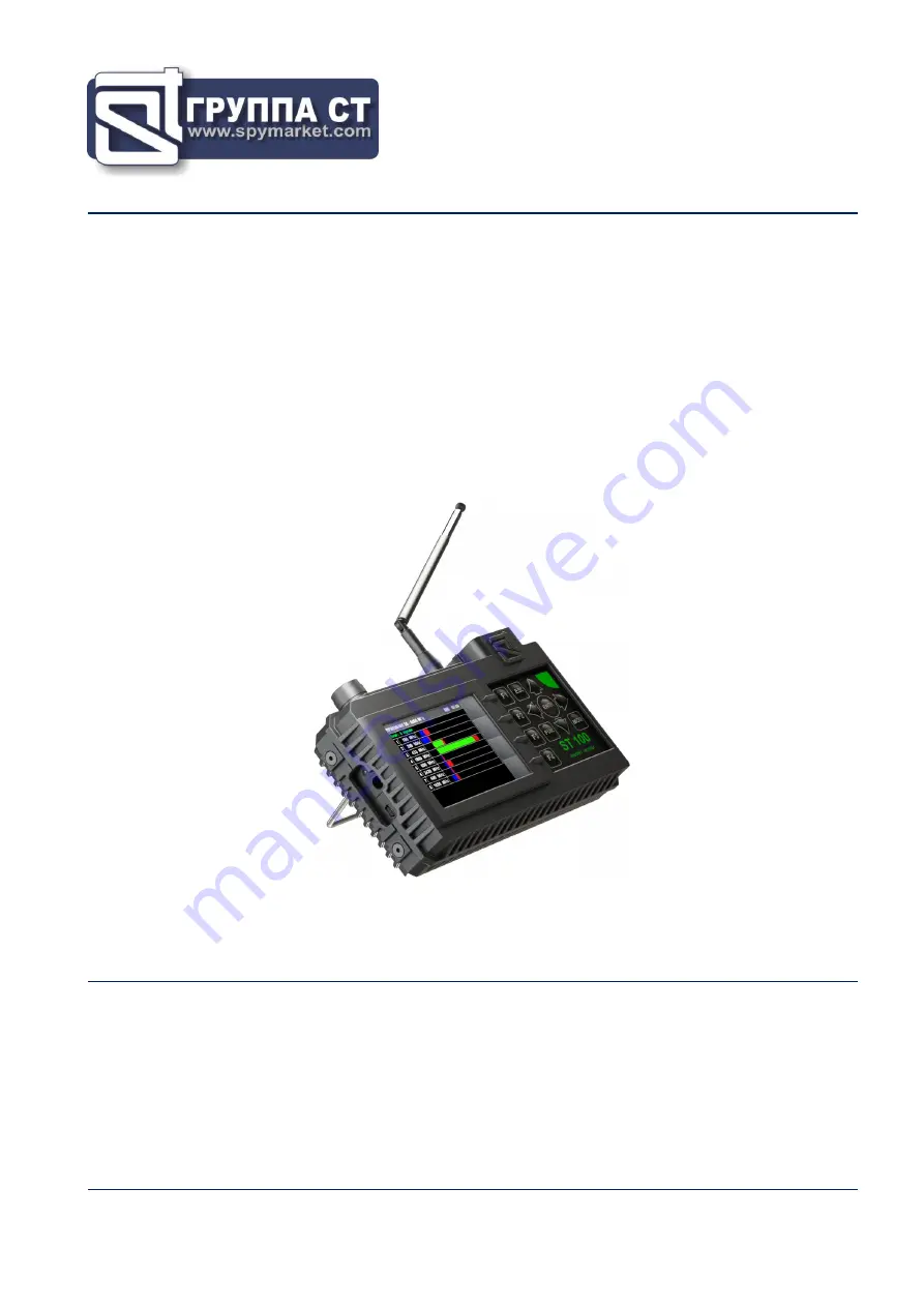
background image


ST 100 

NEARFIELD SEARCH RECEIVER 


USER MANUAL 


ST Group, Ltd. 
St. Petersburg, Russia   
+7 (812) 412-3321 
[email protected] 
www.


spymarket.com 


Summary of Contents for ST 100

Page 1: ...ST 100 NEARFIELD SEARCH RECEIVER USER MANUAL ST Group Ltd St Petersburg Russia 7 812 412 3321 info smersh pro www spymarket com ...

Page 2: ... SEARCH FOR VIDEO CAMERA SIGNALS function 22 3 4 3 OSCILLOSCOPE function 22 3 4 4 SETTING 0 function 22 4 Channel 2 SEARCH RECEIVER 6 GHz 12 GHz 23 5 Channel 3 SEARCH RECEIVER FOR MONITORING THE SELECTED RANGES 24 5 1 MOBILE DEVICES mode 25 5 2 BASE STATIONS mode 26 5 3 USER LIST mode 26 5 4 ANALYSIS OF THE DETECTED SIGNAL function 27 5 5 GAIN SETTING function 29 6 Channel 4 INFRARED DETECTOR 30 6...

Page 3: ...onality 44 9 3 PC system requirements 44 9 4 Installation 44 9 5 SELECTED RANGES mode 46 9 6 MOBILE DEVICES mode 48 9 7 BASE STATIONS mode 51 9 8 USER LIST mode 51 9 9 FIRMWARE UPDATE 51 10 Reference Information 53 Controls 53 Initial settings 53 Channel 1 SEARCH RECEIVER 20 MHz 6 GHz 54 Channel 2 SEARCH RECEIVER 6 GHz 12 GHz 56 Channel 3 SEARCH RECEIVER FOR MONITORING THE SELECTED RANGES 58 Chann...

Page 4: ...equency ranges defined by the user 4 CHANNEL 4 INFRARED DETECTOR designed to detect IR transmitters eavesdropping devices using the IR frequency range for transmission 5 CHANNEL 5 PARAMETRIC DETECTOR designed to detect active digital electronic devices including those without a transmission channel Functionality 1 Search and localization of radio transmitting eavesdropping devices radio microphone...

Page 5: ...s 1 5 Charger for the main unit 1 6 Cable for connecting the main unit to the USB port of the PC 1 7 Parametric detector ST 100 P 1 8 Screws for attaching the parametric detector to the main unit 1 9 Mini antenna 1 10 Case 1 Fig 1 For transportation and storage of the ST 100 the shockproof case is used ...

Page 6: ...d to the numbering presented in item 1 2 1 3 DESCRIPTION OF COMPONENTS 1 3 1 MAIN UNIT Purpose of the main unit analysis of received signals information display control of operating modes Main unit components module for receiving and processing signals display module power supply module governing bodies The main unit is shown in Fig 3 ...

Page 7: ... control 4 Headphone jack 5 Parametric detector connector 6 IR detector sensor 7 Antenna connector 8 Support 9 Serial number plate 10 Connectors for attaching a parametric detector 11 Built in speaker 12 Charger connection indicator 13 Charger socket 14 Mini USB connector for PC connection ...

Page 8: ...f an acoustic signal the correlation of this signal and the information obtained using the ST 100 means that there is an active eavesdropping device with an unencrypted transmission channel in the tested room forced inclusion of eavesdropping devices equipped with a VOX activation system localization of detected eavesdropping devices creation of the masking noise during the search operations MP3 f...

Page 9: ...enna built in IR DETECTOR spectral range μm 0 75 1 1 detection bandwidth MHz 5 angle of view degrees 20 minimum detectable signal strength W Hz1 2 10 13 PARAMETRIC DETECTOR ST 100P frequency range MHz 2000 2100 emitted signal level dBm 20 antenna directional diagram deg 90 antenna polarization elliptical POWER SUPPLY built in lithium polymer accumulator with voltage V 3 7 power consumption W 1 con...

Page 10: ...ess any button on the keyboard for continue 2 2 THE MAIN MENU The MAIN MENU is shown in Fig 5 Fig 5 To turn on any of the menu items use the and buttons to place the table cursor on the corresponding line and press the ENTER To turn on SEARCH RECEIVER 20 6000 MHz SEARCH RECEIVER 6 12 GHz SELECTED RANGES PARAMETRIC DETECTOR you can use the buttons F1 F2 F3 F4 respectively The SETTINGS menu item is ...

Page 11: ...HH MM 2 4 SETTINGS SERVICE MODE This mode is design to set the date time and interface language Russian or English To turn on the mode use the or buttons or in the MAIN MENU to set the tabular cursor to the item SETTINGS and press ENTER For exit to the MAIN MENU press ESC Confirmed parameter changes after exiting the SETTINGS mode are saved including when the power is turned off The screen of the ...

Page 12: ... Exit from the SETTINGS mode without save the changes ESC 2 4 2 TIME SETTING Use the or buttons to set the cursor to the TIME menu item and press ENTER The time setting menu Fig 9 in the HH MM format will appear on the screen Fig 9 The time setting is carried out by analogy with the date setting item 2 4 1 2 4 3 INTERFACE LANGUAGE SETTING To set the interface language use the or buttons set the cu...

Page 13: ... is recommended to use the telescopic antenna for receiving signals in the range of 20 MHz 3 GHz The mini antenna is recommended for receiving signals in the 2 GHz 6 GHz range Any of these antennas can be used to receive signals in the 2 GHz 3 GHz range Antennas are connected to the ANT socket located on the top panel Fig 10 Fig 10 The analysis of the detected signals is performed using graphic in...

Page 14: ...ew bar The PANORAMA mode is automatically started after switching on the channel A panorama of loading the frequency range is displayed on the screen Fig 12 Fig 12 In Fig 12 1 SEARCH RECEIVER 20 MHz 6 GHz is on 2 The value of the frequency at which the marker is set 3 Marker 4 Signal level at the marker frequency 5 Scan step value 6 Bandwidth 7 The maximum signal level at this frequency for all cy...

Page 15: ...e lighter 2 Use the and buttons to set the gain in dB 0 8 16 24 32 40 The set value is displayed on the indicator Fig 13 3 Press F4 The Gain button field will become darker Fig 13 ATTENTION Until the gain setting is completed other modes and functions are unavailable except for switching to the MAIN MENU by pressing the MODE button 3 2 DIFFERENTIAL MODE In DIFFERENTIAL mode the signal levels obtai...

Page 16: ...alysis at a fixed frequency gain adjustment change the view bar DIFFERENTIAL mode controls similar PANORAMA mode controls item 3 1 Turning off the DIFFERENTIAL mode and switching to the PANORAMA mode is made by pressing the F3 button the field of which will become darker The gain and range values set in DIFFERENTIAL mode are retained 3 2 1 SIGNAL ANALYSIS AT A FIXED FREQUENCY FUNCTION The function...

Page 17: ...0 KHz 1 MHz 20 MHz ability to use FM demodulator listening to demodulated signal signal analysis with an oscilloscope localization of the signal source by the energy method Controls Button Action ESC ENTER Turn off the function return to the previous mode MODE Switch to MAIN MENU Marker control F1 Turn on SETTING 0 function F2 Setting the bandwidth and turning on the FM demodulator F3 Turn on OSCI...

Page 18: ...e signal level at the fixed frequency is zeroed and the difference level is displayed on the indicator To turn on the function press the F1 the field of button will become lighter When using the SETTING 0 function it is possible to change the bandwidth value F2 turn on OSCILLOSCOPE F3 change the gain value F4 To turn off the function press the F1 again The F1 button field will become darker 3 2 3 ...

Page 19: ...nal are analyzed for their correspondence to the parameters of the signals from video cameras If the comparison is positive the video camera detection indicator appears in the information line Fig 6 item 2 3 3 LOCALIZATION MODE The mode is intended for localization of radio signal sources in the tested room Moving around the room the user observes the change in the levels of several of the most po...

Page 20: ... whose amplitude exceeds the adaptive detection threshold The mode is turn on from DIFFERENTIAL mode or PANORAMA mode by pressing F2 button The search for signals is performed within the established range taking into account the results obtained in the DIFFERENTIAL mode if the AUTOMATED mode was switched on from the DIFFERENTIAL mode All detected signals are assigned one of three attributes The de...

Page 21: ...ble ascending signal level or frequency 4 Total quantity of signals detected 5 Bandwidth 6 Frequency of detected signals 7 Levels of detected signals 8 Indicator of the position of the table cursor relative to the number of rows 9 Table cursor 10 Signal level at which the table cursor is set Functionality sorting of detected signals by frequency or by level identification of analog signals from TV...

Page 22: ... on FREQUENCY TUNING function 3 4 1 FREQUENCY TUNING FUNCTION To tuning the frequency move the cursor to the corresponding line and press ENTER A window for setting the frequency will appear on the screen Fig 19 Fig 19 Using the buttons the frequency value is set at which the signal level on the indicator Fig 18 item 10 will be maximum The frequency tuning step depends on the set bandwidth BW Band...

Page 23: ...FUNCTION To analyze the demodulated signal using the OSCILLOSCOPE function use the buttons to set the cursor on the corresponding line and press the F3 button Functionality and controls are described in item 3 2 3 To turn off the OSCILLOSCOPE function press the F3 or ESC 3 4 4 SETTING 0 FUNCTION To localize the source of the detected signal the SETTING 0 function is implemented To turn on it use t...

Page 24: ...ysis of the detected signals is performed using graphic information spectrogram oscillogram table of signals etc acoustic information headphones or built in speaker Channel functional diagram Fig 20 SEARCH RECEIVER 6 GHZ 12 GHZ modes are similar to SEARCH RECEIVER 20 MHZ 6 GHZ modes Fig 11 except There is no possibility changing the gain changing the bandwidth fixed bandwidth 20 MHz automatic dete...

Page 25: ...ls in the ranges specified by the user There is a possibility of separate monitoring of the ranges of mobile devices and base stations if such frequency division is provided by the communication standard By default the ranges of mobile communication systems used in Russia are set the composition and parameters of which can be changed using the software The USER LIST mode allows you to monitor pred...

Page 26: ...ode can be activated from the BASE STATIONS or USER LIST mode by pressing the F1 button The device screen in MOBILE DEVICES mode is shown in Fig 22 Fig 22 In Fig 22 1 SELECTED RANGES is on 2 MOBILE DEVICES mode is on light background 3 Table cursor 4 List of digital communication standards 5 Signal levels The current signal level is green The maximum signal level in the range for the entire operat...

Page 27: ...3 Fig 23 Controls Button Action ESC MODE Switch to MAIN MENU ENTER Turn on ANALYSIS OF THE DETECTED SIGNAL function Table cursor control F1 Turn on MOBILE DEVICES mode F3 Turn on USER LIST mode F4 Turn on off GAIN SETTING function FUNC F2 Not used 5 3 USER LIST MODE The mode allows to detect the activity of radio transmitters in the preset frequency ranges and analyze the detected signals The mode...

Page 28: ...T modes allow you to fix signals and determine their level However it is impossible to accurately determine the quantity of signals in each band and the frequency of signals The ANALYSIS OF THE DETECTED SIGNAL function is designed to determine frequencies in the standard bands and analyze them using the OSCILLOSCOPE function To localize the signal source use the SETTING O option which can be turn ...

Page 29: ...cy The screen is divided into three windows SIGNAL LEVEL INDICATOR Fig 25 item 12 OSCILLOSCOPE Fig 25 item 5 SPECTRUM ANALYZER Fig 25 item 8 The INDICATOR window displays the signal level at the marker frequency Fig 25 item 7 of SPECTRUM ANALYZER The other two windows Fig 25 item 5 and item 8 display the oscillogram and the spectrogram Only one window is active at a time which is highlighted with ...

Page 30: ...e the ENTER button to turn the SETTING 0 function on or off Controls Button Action MODE Switch to MAIN MENU ESC Return to the previous mode ENTER Turn on off SETTING 0 function OSCILLOSCOPE SPECTRUM ANALYZER switching Scaling the horizontal axis in OSCILLOSCOPE or Marker Control in SPECTRUM ANALYZER FUNC F1 F2 F3 F4 Not used 5 5 GAIN SETTING FUNCTION The gain setting procedure is described in item...

Page 31: ...scillogram and received signal level indicator acoustic information headphones or built in speaker Switching on is carried out from the MAIN MENU item 2 2 The device screen after switching on the channel is shown in Fig 26 Fig 26 In Fig 26 1 INFRARED DETECTOR is on 2 Received signal level indicator 3 Division value of the time axis horizontal axis 4 Oscillogram Controls Button Action ESC MODE Swit...

Page 32: ...IR signal When the mode is turned on the level of the detected signal is taken as 0 and the differential signal level is displayed on the level indicator Fig 25 item 2 To turn on the DIFFERENTIAL mode press the ENTER The indicator color will turn purple Fig 27 To turn off the DIFFERENTIAL mode press the ENTER button again ...

Page 33: ...ied out on the basis of the acoustic information heard in the headphones The directional antenna allows you to locate the source of the reflected signal The distance to it is determined by the change in the signal volume level the closer to the source the louder the signal The detection range of working digital devices is from 30 to 100 cm Composition of the ST 100P module transmitter forming a hi...

Page 34: ...8 as shown in Fig 29 A In Fig 29 B the parametric detector is installed on the main unit Fig 29 A Fig 29 В Attention The parametric detector cable connector is equipped with a clamp To disconnect the connector press the button Fig 30 Fig 30 The detector antenna has an elliptical 90 radiation pattern Fig 31 Fig 31 ...

Page 35: ...The screen of the device after switching on is shown in Fig 32 Fig 32 At the same time the transmitter and receiver of the parametric detector are turned on the sound is heard in the headphones Controls Button Action ESC MODE Switch to MAIN MENU F1 F2 F3 F4 ENTER FUNC Not used ...

Page 36: ... 6 GHz or 6 GHz 12 GHz 3 Set the optimal gain without overscaling only for receiver 20 MHz 6 GHz 4 Turn on the AUTOMATED mode 5 Sort the table in ascending order of signal level and set the cursor on the first row 6 Analyze the demodulated signal listen to the signal at different values of the bandwidth only for receiver 20 MHz 6 GHz analyze the signal on an oscilloscope fine tune the frequency if...

Page 37: ...alyze the signal on an oscilloscope fine tune the frequency if necessary Signs of DANGEROUS signals the test sound is heard at the frequency of the detected signal the test sound is not audible the oscillogram of the demodulated signal changes when the test sound changes the level of the detected signal increases when entering the tested room 8 Analyze other signals in the same way 8 1 3 SIGNAL SO...

Page 38: ...ately the same It will be difficult to determine where the signal strength is at its maximum Setting the gain to minimum will also not solve this problem It is recommended to carry out localization with the antenna turned off In most cases this will allow you to determine the location of the GSM device Features of the energy method when using the LOCALIZATION mode the ability to simultaneously mon...

Page 39: ...nge a table Fig 17 with information about the detected signals is displayed on the screen which displays their serial numbers frequencies and siugnal levels in graphical form Signal levels fixed when the device is turned on are taken as 0 as in the DIFFERENTIAL mode When the device move around the room the signal levels will change depending on the distance to their sources The level of one of the...

Page 40: ...splayed in blue Fig 35 item 2 As you approach the signal source the signal level relative to the 0 level will increase The width of the green sector will increase Fig 35 item 3 The maximum signal level fixed in the current session is displayed in burgundy In Fig 35 item 4 the current level green is below the previously fixed maximum level burgundy In Fig 35 item 5 the current level blue is below t...

Page 41: ...eviously checked point The device is approaching the signal source 6 Move the device in the direction of increasing signal strength Highest signal level The device is approaching the signal source 7 Move the device along the wall from point 6 Signal level is lower than point 6 The device moves away from the signal source The maximum signal level was fixed at point 6 Further searches should be cont...

Page 42: ...et the cursor on the corresponding line and turn on the ANALYSIS OF THE DETECTED SIGNAL function Signs of a DANGEROUS signal in MOBILE DEVICES mode high level of the detected digital signal in the absence of legal communication devices in the near zone the time frequency structure of the signal does not correspond to the standard structure when analyzing the signal using an oscilloscope detected a...

Page 43: ...e IR transmitter is opposite the window 8 3 1 SEARCH FOR SIGNALS The search for the eavesdropping device must be started from the window directing the IR sensor towards the intended location of the IR transmitter It should be borne in mind that the detection range of the IR detector is 50 70 cm Search algorithm 1 Turn on the the PTS in tested room 2 Turn on the IR DETECTOR 3 Direct the IR sensor t...

Page 44: ...e the volume control to set a comfortable sound level in the headphones 6 Aim the antenna towards the probed area Fig 31 7 Moving the device in space monitor the signal with headphones If there are no working digital devices in the probed area acoustic background will be heard in the headphones If various signals are heard in the headphones crackling clicks whistling etc then a working digital dev...

Page 45: ...d data to the ST 100 Files on the HDD are saved in the xxx dat format xxxx is the file name assigned by the user when saving Only one file can be loaded into the ST 100 An unlimited number of files can be saved to the HDD 9 3 PC SYSTEM REQUIREMENTS Operating system Windows 7 8 10 64 bit Free space on hard disk at least 100 Mb 9 4 INSTALLATION The software distribution kit is located in the Prog_ST...

Page 46: ... 1 USB connected the main unit is turned on and connected to the PC 2 Request to connect to ST100 the PC sends a request to connect the main unit the driver is installed the main unit is turned off and connected to the PC 3 No response from ST100 there is no response from ST 100 the main unit is not connected to the PC or it is turned off or the driver is not installed MODES 1 SELECTED RANGES 2 MO...

Page 47: ...eration of various standard radio equipment etc After downloading to the ST 100 information about the DANGEROUS and NON DANGEROUS ranges the signals displayed in the AUTOMATED mode table item 3 4 will be highlited with the corresponding colors Signals detected in the DANGEROUS range are highlighted in red in the NON DANGEROUS range in green The rest of the signals are classified as UNKNOWN and are...

Page 48: ...ELECTED RANGES MODE 1 Go to the Selected Ranges tab 2 Download data in any of the following ways From the HDD Press Load from File button and specifying the path to the required file All information will be downloaded including data on the selected ranges From ST100 Press Read ALL from ST100 button All information will be downloaded including data about the selected ranges Press Read from ST100 bu...

Page 49: ...he cursor on the corresponding line and press the Delete button After confirming the deletion the line is removed from the list Shutting down Before completing you must save the changes in any of the following ways Save to the PC HDD Press the Save to File button and specifying the path for saving and the file name information about the selected ranges and information from other modes will be save...

Page 50: ... the Mobile devices mode 4 initial frequency of the range input field 5 ending frequency of the range input field 6 range title input field only numbers and Latin letters 7 range delete button 8 buttons for confirmation and cancellation of the adjustments 9 button for loading factory settings the list of ranges of digital communication mobile devices used in Russia is loaded OPERATION IN MOBILE DE...

Page 51: ... parameters of the new range initial and or ending frequency Fig 39 item 4 and item 5 title of the range Fig 39 item 6 sign of activity Fig 39 item 2 3 Press the Apply Changes button to save the information about the new range or the Cancel button to exit without saving Restrictions when adjusting and adding ranges 1 The maximum number of ranges lines in the list is 11 2 The range should not excee...

Page 52: ...for loading correcting saving data and restrictions are the same as described in the OPERATION IN MOBILE DEVICES MODE section 9 8 USER LIST MODE The mode is intended for creating and correcting the list of frequency ranges in which the signals of interest to the user are located This information downloded to the ST 100 memory is used when the channel SELECTED RANGES is operating in the USER LIST m...

Page 53: ...x_xx bin x_xx version number to the HDD of the PC 2 Run the ST 100 program on the PC 3 Connect the ST 100 main unit to the PC 4 Go to the FIRMWARE UPDATE tab 5 Press Browse button 6 In the window that appears specify the path to the file with the new firmware and press the OPEN button The field Fig 41 item 2 will display the file name and path to it 7 Press UPDATE button The progress of the update...

Page 54: ...ETECTOR Table cursor control ENTER Confirm action SETTINGS Table cursor control ENTER Confirm action ESC Exit to MAIN MENU To change the interface language set the cursor on the ENGLISH or РУССКИЙ menu item and press ENTER SETTING THE DATE Choice of a position Correction of value ENTER Save and exit ESC Exit without saving SETTING THE TIME Choice of a position Correction of value ENTER Save and ex...

Page 55: ...e to the set frequency on the marker Frequency tuning F1 Turn on LOCALIZATION mode F2 Turn on AUTOMATED mode F3 Turn on off DIFFERENTIAL mode F4 Turn on Gain setting ENTER Turn on SIGNAL ANALYSIS AT A FIXED FREQUENCY function FUNC Not used SIGNAL ANALYSIS AT A FIXED FREQUENCY function MODE Switch to MAIN MENU ESC ENTER Turn off the function step back Frequency tuning F1 Turn on off SETTING 0 funct...

Page 56: ...n to the previous mode FUNC Sorting the table ascending frequency or signal level ENTER Turn on FREQUENCY TUNING function Cursor control F1 Turn on off SETTING 0 function F2 Setting the bandwidth and turning on the FM demodulator F3 Turn on the OSCILLOSCOPE function F4 Turn on Gain setting AUTOMATED mode FREQUENCY TUNING function MODE Switch to MAIN MENU ESC ENTER Turn off FREQUENCY TUNING functio...

Page 57: ...U ESC Off mode step back Cursor control ENTER Вкл SIGNAL ANALYSIS AT A FIXED FREQUENCY function F1 F4 FUNC Not used CHANNEL 2 SEARCH RECEIVER 6 GHZ 12 GHZ PANORAMA mode DIFFERENTIAL mode ESC MODE Switch to MAIN MENU Scaling Zoom Scaling Zoom Scaling occurs relative to the set frequency on the marker Frequency tuning F1 Turn on LOCALIZATION mode F2 Turn on AUTOMATED mode F3 Turn on off DIFFERENTIAL...

Page 58: ...NORAMA mode SIGNAL ANALYSIS AT A FIXED FREQUENCY OSCILLOSCOPE functions MODE Switch to MAIN MENU ESC F3 OSCILLOSCOPE function Time axe scaling F1 F2 F4 ENTER FUNC Not used AUTOMATED MODE AUTOMATED mode MAIN TABLE MODE Switch to MAIN MENU ESC Return to the previous mode FUNC Sorting the table ascending frequency or signal level ENTER Turn on FREQUENCY TUNING function Cursor control F1 Turn on off S...

Page 59: ... Turn off the OSCILLOSCOPE function Time axe scaling F1 F2 F4 ENTER FUNC Not used LOCALIZATION MODE MODE Switch to MAIN MENU ESC Off mode step back Cursor control ENTER Turn on the SIGNAL ANALYSIS AT A FIXED FREQUENCY function F1 F4 FUNC Not used CHANNEL 3 SEARCH RECEIVER FOR MONITORING THE SELECTED RANGES MOBILE DEVICES mode MODE ESC Switch to MAIN MENU Cursor control ENTER Turn on ANALYSIS OF TH...

Page 60: ...e F4 Turn on Gain setting F3 FUNC Not used ANALYSIS OF THE DETECTED SIGNAL function OSCILLOSCOPE function MODE Switch to MAIN MENU ESC Off mode step back Turn on SPECTRUM ANALYZER function ENTER Turn on off SETTING 0 function Time axe scaling F1 F4 FUNC Not used ANALYSIS OF THE DETECTED SIGNAL function SPECTRUM ANALYZER function MODE Switch to MAIN MENU ESC Turn off the mode step back Turn on the ...

Page 61: ...Reference information Controls 60 CHANNEL 5 PARAMETRIC DETECTOR MODE ESC Switch to MAIN MENU ENTER F1 F4 FUNC Not used ...

Reviews: