(f) The operating switch disconnects the filament battery and the "B" voltage to the volume control. This
prevents unnecessary "B" battery consumption when the receiver is not in use.
(g) A fixed regenerative detector gives added sensitivity to that circuit with a resulting gain in over-all
sensitivity. This does not require any adjustment during operation.
PART I—INSTALLATION
Information on the various points dealing with installation as listed below can be obtained by referring to the
Service Notes or Instruction Books mentioned. This information has been repeatedly published in past issues of
Service Notes, and the average service man is probably so familiar with it, that further details are unnecessary.
The Radiola
22
has two red wood screws to hold the reproducer unit during
shipment. Be sure
that these
are removed as otherwise acoustic howling may result.
Antenna (Indoor or outdoor).—See R-44 and 46 Service Notes.
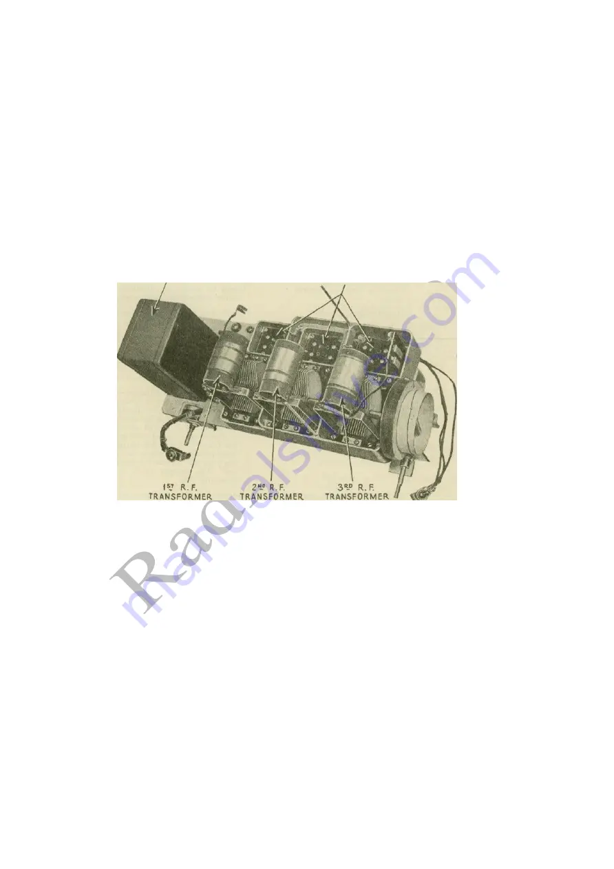
RADIOTRON SOCKETS FOR, 1
st
and 2
nd
R.F. AND DETECTOR.
Figure
4
—
View of receiver with shields removed
Ground.—See R-44 and 46 Service Notes.
Shields.—See R-44 and 46 Service Notes.
Batteries and Connections.—See R-21 or 22 Instruction Book.
PART II—SERVICE DATA
Service data on the following subjects can be obtained from the
Service
Notes mentioned below:
Antenna system failures.—See R-44 and 46 Service Notes.
Radiotron sockets and prongs.—See R-44 and 46 Service Notes.
Broken condenser drive cord.—See R-44 and 46 Service Notes.
Adjusting R.F. line-up condensers.—See R-44 and 46 Service Notes.
Service data on reproducer unit.—See R-100A or R-100B Service Notes.
7
INTERSTAGE
COUPLING UNIT


