background image


RCA RADIOLAS 21 and 22 

SERVICE NOTES Prepared by RCA Service 

Department


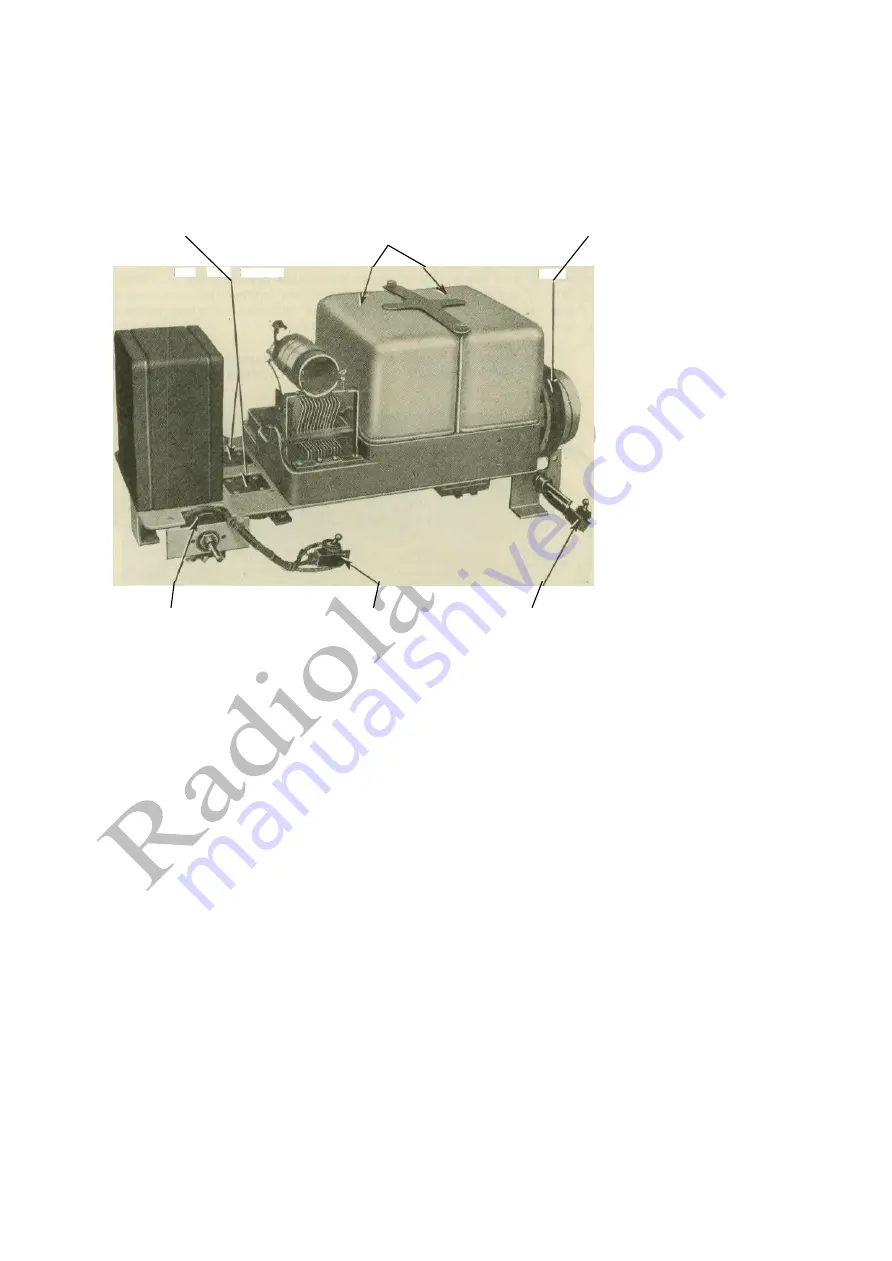
STAGE SHIELDS


VOLUME CONTROL                    LOCAL-DISTANT SWITCH          OPERATING SWITCH 

Figure 2—Top view of receiver chassis showing location of some parts


ELECTRICAL AND PHYSICAL SPECIFICATIONS


Type of receiver—Screen Grid Tuned R.F. Battery. 

Recommended Antenna Length—35—60 feet. 

Type of Filament Power—Storage Battery or Eliminator. 

Type of Plate and Grid Power—"B" and "C" Batteries or 

Eliminator. 

  Number and Type of Tubes—Two UX-222, 

2

 UX-112A, 

1 UX-112A or UX-171A— Total 5. 

  Number of R.F. Stages—Two. 
  Type of Detector—Grid condenser and leak. 
  Number of A.F. Stages—Two. 
  Type of Loudspeaker (R22 only)—

Magnetic.


5

RADIOTRON SOCKETS 

FOR A.F. STAGES


STATION 

SELECTOR DIAL 

Height ........ 
Depth ......... 
Width ........ 
Weight, 

alone 

Weight,      packed 

R21 

10.5 inches 
10.0 " 
20.5 " 
27 Ibs. 
40 Ibs. 

R22 

40.5 inches 
22.0

 " 

21.5" 
44 

Ibs. 

105 lbs. 

Summary of Contents for Radiola 21

Page 1: ...Copyright October 1929 RADIO VICTOR CORPORATION OF AMERICA 233 BROADWAY NEW YORK CITY DISTRICT SERVICE STATIONS BROOKLYN N Y CHICAGO ILL SAN FRANCISCO CAL Bldg No 19 168 39th St 2001 West Pershing Road 274 Brannan St DALLAS TEXAS ATLANTA GA Santa Fe Bidg Unit No 2 150 Peters St ...

Page 2: ...ase of the Dealer and Distributor s business the RCA Service Department has prepared a series of Service Notes of which this booklet is a part containing technical information and practical helps in servicing RCA Loudspeakers and Radiolas This information has been compiled from experience with RCA Dealers and Distributors service problems and presents the best practice in dealing with them A caref...

Page 3: ...Voltage Readings 10 Radiola 21 or 22 Continuity Tests 11 Continuity Test Charts 13 15 PART IV MAKING REPLACEMENTS Removing Chassis from Cabinet of Radiola 21 16 Removing Reproducer from Radiola 22 16 Removing Receiver Assembly from Radiola 22 16 Replacing R F Line up Condensers 16 ILLUSTRATIONS RCA Radiola 21 1 Schematic Circuit Diagram of Radiolas 21 and Rear Interior Cabinet View of Radiola 22 4...

Page 4: ...Figure 1 Rear interior cabinet view of Radiola 22 4 RECEIVER ASSEMBLY REPRODUCER UNIT ANTENNA AND GROUND LEADS BATTERY CABLE ...

Page 5: ...ngth 35 60 feet Type of Filament Power Storage Battery or Eliminator Type of Plate and Grid Power B and C Batteries or Eliminator Number and Type of Tubes Two UX 222 2 UX 112A 1 UX 112A or UX 171A Total 5 Number of R F Stages Two Type of Detector Grid condenser and leak Number of A F Stages Two Type of Loudspeaker R22 only Magnetic 5 RADIOTRON SOCKETS FOR A F STAGES STATION SELECTOR DIAL Height De...

Page 6: ...ew of receiver Circuit features see Figure 6 of these Radiolas are a Screen grid battery receiver giving sensitivity and selectivity comparable to that obtained with A C type screen grid receivers b Circuit consists of two tuned R F stages tuned grid leak type detector first audio stage and second audio stage employing a choice of power tubes c Local distant switch provides best reception on both ...

Page 7: ...necessary The Radiola 22 has two red wood screws to hold the reproducer unit during shipment Be sure that these are removed as otherwise acoustic howling may result Antenna Indoor or outdoor See R 44 and 46 Service Notes RADIOTRON SOCKETS FOR 1st and 2nd R F AND DETECTOR Figure 4 View of receiver with shields removed Ground See R 44 and 46 Service Notes Shields See R 44 and 46 Service Notes Batter...

Page 8: ... Check by using another loudspeaker known to be in good operating condition and make any replacement necessary Defective Radiotrons Defective interstage A F transformer output choke output condenser or other parts Receiver oscillation Test and replace any defective Radiotron Check parts by means of continuity test and make any replacement necessary Should the Radiolas oscillate all signals will be...

Page 9: ...not stop clean points of contact between base and all shields Ground local distant switch properly Bend shield contact clips so that a good firm contact is made to the condenser rotor shaft An open by pass condenser or one improperly connected may cause oscillation Check and replace if necessary A defective Radiotron UX 222 may cause oscillation Interchanging with one known to l e in good conditio...

Page 10: ...op is permissible before renewal is necessary Individual batteries may be tested by dis connecting entirely and reading with a voltmeter The B batteries should be discarded when their voltage is less than 34 volts per block The C batteries should be renewed with the B batteries A storage A battery requires charging when the voltage is below 5 4 for a battery or 1 8 per cell under load SOCKET VOLTA...

Page 11: ... pair of headphones with at least 4 2 volts in series or a voltmeter with sufficient battery to give a good deflection when connected across the battery terminals should be used in making these tests The resistance of the various circuits are also shown in the column titled Correct Effect Checking the resistance of the circuits adds an additional check on their correct functioning This may be done...

Page 12: ...gure 7 Radiola 22 battery cable and external connections of receiver assembly and reproducer unit 11 OPERATIN6 SWITCH TO GROUND TO ANTENNA LOCAL DISTANT SWITCH B PWR B AMP 135 V B 67 V C AMP 9V C PWR A 6V ...

Page 13: ...g condenser Stator tuning condenser No 3 to Ground Closed 3 Ohms Open Short former Shorted tuning or trimming condenser G4 to C 9 Black and Green Closed 5 500 Ohms Open Open secondary of 1st A F transformer G5 to C Pwr B lack wit h Green tracer Closed 5 500 Ohms Open Open secondary of 2nd A F transformer Plate PI to B 135 Maroon and Red Closed 60 Ohms Open Open primary of 2nd R F transformer P2 to...

Page 14: ...Figure 8 Wiring diagram showing color code and connections ...

Page 15: ...o A Yellow Closed 1 95 Ohms Open Open 1 95 ohm resistor or connection F4 to A Yellow Closed 1 95 Ohms Open Open 1 95 ohm resistor or connection F5 to A Yellow Closed 1 55 Ohms Open Open 1 55 ohm resistor or connection Misc Antenna to ground Switch at distant position Closed 30 Ohms Open Open connection antenna loading coil or primary of first R F transformer B 67 Maroon to A Black with Yellow trac...

Page 16: ... R 22 RECEIVER ASSEMBLY To remove the receiver assembly of Radiola 22 proceed as follows a Release the operating switch and local distant switch by removing their escutcheons and releasing the switch collar Replace the escutcheons temporarily b Remove the station selector and volume control knobs c Release the antenna and ground leads and the battery cable Remove the loudspeaker connections from t...

Reviews: