SERVICE MANUAL
1.7 Analog switch circuit HEF4053BP
1.7.1
Description
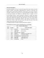
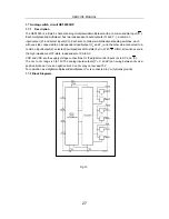
The HEF4053 is a triple 2-channel analog multiplexer/demultiplexer with a common enable input (
E
).
Each multiplexer/demultiplexer has two independent inputs/outputs (Y
0
and Y
1
), a common
input/output (Z), and select inputs (Sn). Each also contains two-bidirectional analog switches, each
with one side connected to an independent input/output (Y
0
and Y
1
) and the other side connected to a
common input/output(Z). selected (low impedance ON-state) by Sn. With
E
HIGH, all switches are in
the high impedance OFF-state, independent of SA to SC.
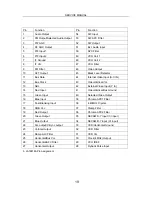
VDD and VSS are the supply voltage connections for the digital control inputs (S
A
to SC and
E
).
The V
DD
to V
SS
range is 3 to 15V.The analog inputs/outputs (Y
0
, Y
1
and Z) can swing between V
DD
as a
positive limit and V
EE
as a negative limit. V
DD
-V
EE
may not exceed 15 V.
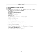
For operation as a digital multiplexer/demultiplexer, V
EE
is connected to V
SS
(typically ground).
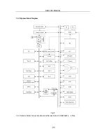
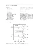
1.7.2 Block Diagrams
Fig.15
27
Summary of Contents for MCR51R410
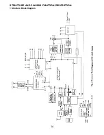
Page 15: ...14 STRUCTURE AND CHASSIS FUNCTION DESCRIPTION 1 Structure Block Diagram ...
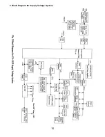
Page 16: ...15 2 Block Diagram for Supply Voltage System ...
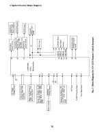
Page 17: ...16 3 System Control Block Diagram ...
Page 38: ......
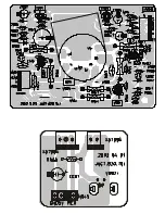
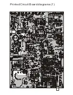
Page 39: ...Printed Circuit Board diagrams 1 ...
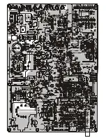
Page 40: ......
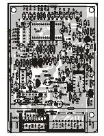
Page 41: ......

