background image

7

8

SLEEP

P

.

MODE

S

.

MODE

LIST

1

2

3

SOURCE

+-./

ABC

DEF

DTV

Installing Batteries in the Remote Control

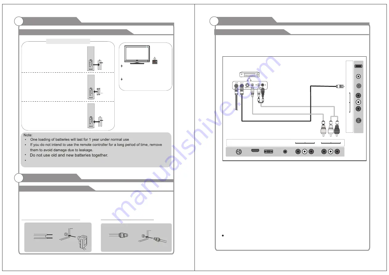
Installing Batteries

Installing Batteries

1

Open the battery compartment 

cover on the back side.

2

Insert two 1.5V AAA  size batteries in

correct polarity. Don´t mix old or used

batteries with new ones.

3

Closed the cover.

Point the remote towards the remote 

control sensor of the wireless TV and 

use it within 7 meters.

Put the used batteries into the recyc-

ling bin since it can negatively affect

the environment.

General Description

Battery

Cover

2

xsize


AAA

 1.5

V

Battery
Cover

Antenna connection

Antenna input impedance of this unit is 75ohm. VHF/UHF 75ohm coaxial cable can be 

connected to the antenna jack directly, if the antenna cable is 300ohm parallel flat feeder 

cable, you need to use the 300ohm/75ohm converter to connect the antenna cable to the 

antenna jack. For details Please refer to the following drawing.

Use a 75ohm - 300ohm converter

300ohm coaxial cable

Antenna feeder

ANT IN

75ohm coaxial cable

Antenna cable

Antennas with 300ohm flat twins Leads

Antennas with 75ohm Round Leads

External Connection

The


batteries


shall


not


be


eposed


to


ecessive


heat


such


as


sunshine


fire


of


the


like.

External Connection

Connecting VCR

These instructions assume that you have already connected your TV to an antenna or a 

cable TV system. Skip step 1 if you have not yet connected to an antenna or a cable 

system. 

Follow the instructions in Viewing a VCR or Camcorder Tape to view your VCR tape. 

  Each VCR has a different back panel configuration. 

  When connecting a VCR, match the color of the connection terminal to the cable. 

  We recommend the use of cables with a Ferrite Core.

1. Unplug the cable or antenna from the back of the TV.

2. Connect the cable or antenna to the ANT IN terminal on the back of the VCR.

3. Connect an RF Cable between the ANT OUT terminal on the VCR and the ANT IN  

    terminal on the TV.

4. Connect a Video Cable between the VIDEO OUT jack on the VCR and the VIDEO IN

    jack on the TV.

5. Connect Audio Cables between the AUDIO OUT jacks on the VCR and the AUDIO L and 

    AUDIO R jacks on the TV. 

        If you have a mono (non-stereo) VCR, use a Y-connector (not supplied) to hook up to 

        the right and left audio input jacks of the TV. If your VCR is stereo, you must connect 

        two cables.

VCR Rear Panel

Audio Cable (Not supplied)

Video Cable (Not supplied)

RF Cable (Not supplied)

HDMI 

IN

VGA 

IN

VIDEO

 IN

PC

AUDIO

IN

DC 12V 

IN

Pr 

Pb 

Y

 IN

R

F

 I

N

E

A

R

P

H

O

N

E

 O

U

T

U

S

L


C

O

A

X

IA

L

O

U

T

S

-V

ID

E

O

IN

Summary of Contents for DECK15DR

Page 1: ...For Sales Information Please Contact RoadTrucker Inc www RoadTrucker com 8312 Sidbury Rd Wilmington NC 28411 800 507 0482 910 686 4281 ...

Page 2: ......

Page 3: ...hat can hold the weight of TV And if possible secure the TV according to the instruction below Note The fastening components such as screws are not supplied with TV Step one Insert the M4 mounting screws into the upper two wall mounting screw holes and fasten them Figure A Step two Insert anchors to wall and connect the bolts and anchors with ropes or chains Figure B Figure A Figure B M4 Screws Wa...

Page 4: ... The exclamation point within an equilateral triangle is intended to alert the user to the presence of important operating and maintenance servicing instructions in the literature accompanying the TV FCC Notice FCC Information High voltages are used in the operation of this television receiver Do not remove the cabinet back from your set Refer servicing to qualified service personnel To prevent fi...

Page 5: ...neral Description Overview of front and side panel Overview of back panel Overview of remote control 4 4 7 4 5 6 External Connection Connecting VCR 9 10 8 PICTURE SOUND 18 Basic operation Turning the TV On and Off 15 15 16 OSD Menu Operations BASIC OPERATION 16 17 Picture defects and the reason 26 8 SETUP CHANNEL 19 20 Connecting DVD Player Set Top Box via HDMI Connecting DVD Player Set Top Box Co...

Page 6: ...ER REMOTE CONTROL SENSOR Aim the remote control towards this spot on the TV POWER INDICATOR Green In power on mode Red In standby mode Toggles between all the available input sources TV AV S VIDEO Component CH Press to change channels In the on screen menu use the CH buttons as up down arrow buttons VOL Press to increase or decrease the volume In the on screen menu use the VOL buttons as left righ...

Page 7: ... select signal source for TV VOL Press these two buttons to increase decrease the sound volume CH Press these two buttons to change channels sequently enter Allows you to navigate the on screen menus and adjust the system settings to your preference EXIT Exit from the menu or sub menu MENU Allow you to navigate the on screen menus EPG Press to display EPG Electronic Program Guide in formation INFO...

Page 8: ...be eposed to ecessive heat such as sunshine fire of the like External Connection Connecting VCR These instructions assume that you have already connected your TV to an antenna or a cable TV system Skip step 1 if you have not yet connected to an antenna or a cable system Follow the instructions in Viewing a VCR or Camcorder Tape to view your VCR tape Each VCR has a different back panel configuratio...

Page 9: ... jacks on 2 Connect Audio Cables between the COMPONENT IN R AUDIO L jacks on the TV Connecting Digital Audio System The rear panel jacks on your TV make it easy to connect a Digital Audio System to your TV 5 1 CH audio is possible when the TV is connected to an external device supporting 5 1 CH We recommend the use of cables with a Ferrite Core 1 Connect an COAXIAL Cable between the SPDIF jacks on...

Page 10: ...connection can only be made if there is a HDMI Output connector on the external device What is HDMI HDMI or high definition multimedia interface is a next generation interface that enables the transmission of digital audio and video signals using a single cable without compression Multimedia interface is a more accurate name for it especially because it allows multiple channels of digital audio 5 ...

Page 11: ...ll be muted D Sub Cable Not supplied PC Phone In HDMI IN VGA IN R L VIDEO IN PC AUDIO IN DC 12V IN Pr Pb Y IN RF IN EARPHONE OUT USB R L COAXIAL OUT S VIDEO IN 3 Connect the PC audio input jackc on the TV Input Mode Air Cable 8VSB Free 64 256QAM CVBS NTSC 3 58 Supporting signals Component VGA PC 480p 60Hz 720p 60Hz 1080i 60Hz HDMI 640x480 60Hz 800x600 60Hz 1024x768 60Hz 480p 60Hz 720p 60Hz 1080i 6...

Page 12: ...ut 15 minutes Memory before turning TV off The settings of picture and the preset channels will be memorized at turning off the unit When being started up again the unit will work according to the mode set before being turned off 1 How to turn the TV on or off Basic Operation Press SOURCE button to display the input source list Press button to select the input source you want to watch Press ENTER ...

Page 13: ...o select the option and then press to adjust the value in the sub menu NOTE Contrast This item can adjust the highlight intensity of the picture but the shadow of the picture is invariable Brightness This item can adjust the optical fiber output of the entire picture it will effect the dark region of the picture Color This item can adjust the saturation of the color based on your own like Tint Thi...

Page 14: ... to select Enter Password Press button to highlight Time then press the buttons to select Sleep Time Time Zone DST Time style clock Press button to highlight Closed Caption then press buttons to enter sub menu Press button to highlight Menu Settings then press to adjust the value in the sub menu Press button to highlight VGA Settings This is only available in PC source Press button to highlight Re...

Page 15: ... the formats MP3 from the USB device Press button to select the music you want to listen and then press ENTER button to play Press button to select menu in the botton you want to run and then press ENTER bitton to operate Press exit button to back to the previons menu 21 22 USB USB Photo USB C C 001 001 0 0 Bytes 000 x 000 Total Size 3 7 CB Unused Size 3 7 CB USB C jpg Photo dsjf jpg 006822 jpg ds...

Page 16: ...e the current default settings is wide 2 OSD Lang Set the OSD language options 3 CAPTION Play the enclosed captions on some DVD titles Optional settings ON OFF 4 LAST MEMORY Save the last to open with the related options are ON OFF INITIAL SETTING DVD Multi MULTI Default Password is 8888 5 6 7 Default This option will resume the original settings of this player ...

Page 17: ...25 26 Picture defects and the reason 8 MUTE Troubleshooting plugged in been Snowy Picture ...

Page 18: ...27 28 For Sales Information Please Contact RoadTrucker Inc www RoadTrucker com 8312 Sidbury Rd Wilmington NC 28411 800 507 0482 910 686 4281 ...

Reviews: