UM-1096
Revision A
15
Figure 11 Calibration Diagram
Prior to beginning your calibration make sure you have the following items:
1.
A cylinder of calibration gas with concentration equal to the SPAN GAS VALUE setting (RC
Systems typically recommends choosing a value at 50% of full scale.)
2.
A cylinder of Zero Air (unless you are confident there is no target gas potentially present in
the area)
3.
A flow regulator, a fixed flow of 0.5LPM is recommended for most applications, but some
instances may require a 1.0LPM fixed flow regulator.
4.
A Splash Guard with integral Calibration Adapter or Calibration Adapter
Summary of Contents for 10-0517
Page 4: ...UM 1096 Revision A III Drawings 44...
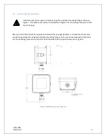
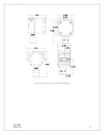
Page 10: ...UM 1096 Revision A 5 Figure 2 Remote Sensor Enclosure Mounting Dimensions...
Page 26: ......
Page 49: ...UM 1096 Revision A 44 Appendix 9 Drawings Drawings Figure 13 Mounting Dimensions...
Page 50: ...UM 1096 Revision A 45 Figure 14 10 0517 CPU Board Figure 15 10 0533 I O Board...
Page 51: ...UM 1096 Revision A 46 Figure 16 10 0532 Modbus Relay Board...

