UM-1096
Revision A
8
3.4.2
SensePoint Relay Option
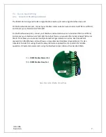
The SensePoint Relay option (
Figure 5
) includes three programmable relays and a single programmable
RS 485 Modbus master or slave port. The relay labeled “FAILSAFE” is set up as a failsafe Fault relay by
default but can be configured as a programmable relay in the
Relay Settings
menu. It is possible to use
only the relays, only Modbus or both.
The relay terminals are labeled NO (Normally Open), NC (Normally Closed) or C (Common, or pole).
These designators correspond to the shelf, or de-energized, state of the relays. When a relay is in
Failsafe mode, it is energized when the alarm condition is not met, and therefore its action is reverse of
the designators.
For the RS-485 Modbus master/slave port, connect your Modbus communication wires to terminals
TB1.A and TB1.B, and connect your shield wire to TB1.SHLD.
TB1
– RS485 Modbus Master/
Slave Port
TB2
– Relay Terminals
TB
2
A B S
TB1
RL
Y 1
RL
Y 2
FL
T
Figure 5 SensePoint Relay Option Wiring
Summary of Contents for 10-0517
Page 4: ...UM 1096 Revision A III Drawings 44...
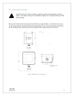
Page 10: ...UM 1096 Revision A 5 Figure 2 Remote Sensor Enclosure Mounting Dimensions...
Page 26: ......
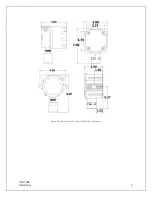
Page 49: ...UM 1096 Revision A 44 Appendix 9 Drawings Drawings Figure 13 Mounting Dimensions...
Page 50: ...UM 1096 Revision A 45 Figure 14 10 0517 CPU Board Figure 15 10 0533 I O Board...
Page 51: ...UM 1096 Revision A 46 Figure 16 10 0532 Modbus Relay Board...


