FenixS– user’s manual
Document Revision: 1.0
September 2021
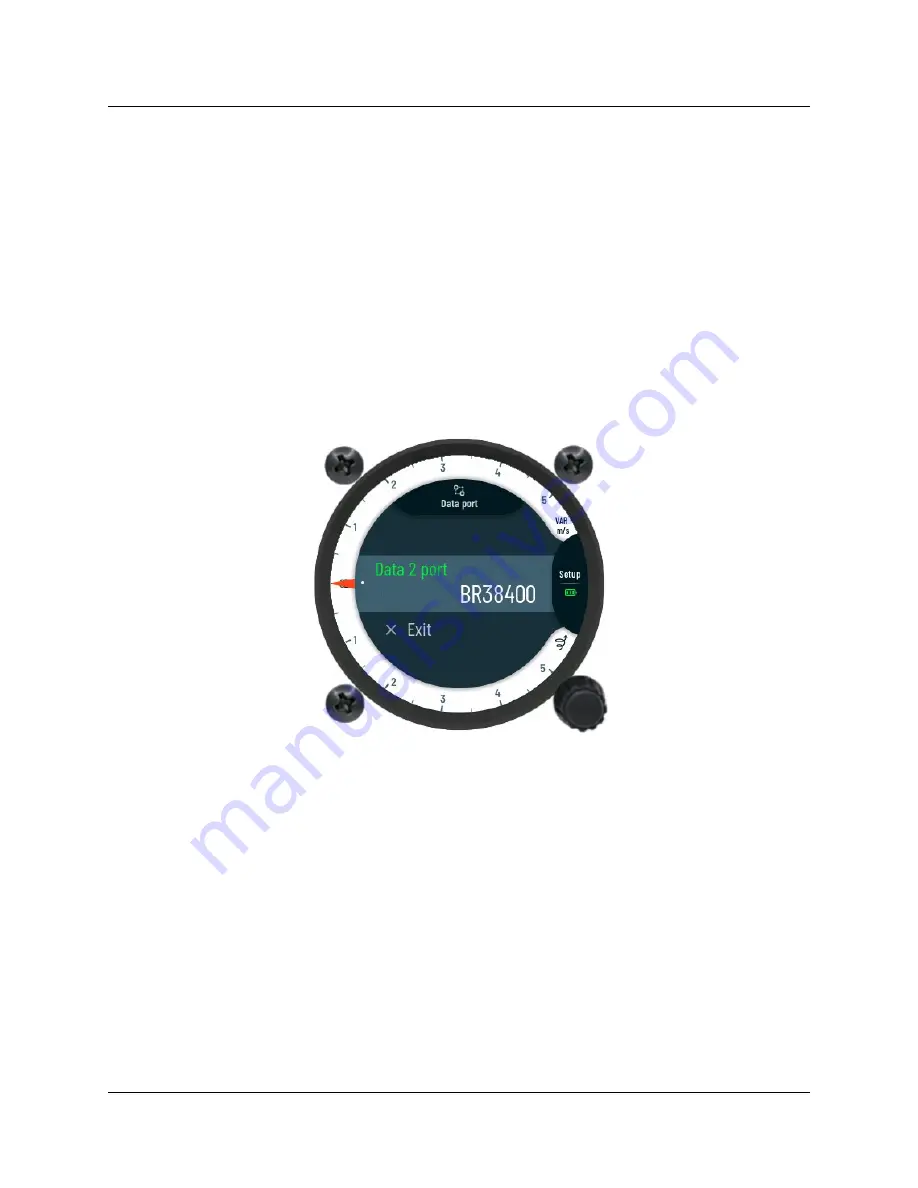
3.3.7 Data port
Working configuration of the external data port is set in sub-page
Data port.
The pilot can set
the following parameter:
Data port 2 –
parameter to set communication speed between the FenixS data port 2
and the externally connected device. The following data speeds can be chosen:
o
BR4800
o
BR9600
o
BR19200
o
BR38400
o
BR57600
o
BR115200
28
Figure 25: Data port sub-page reference.