background image

FenixS– user’s manual

Document Revision: 1.0

September 2021

3.1 Main page

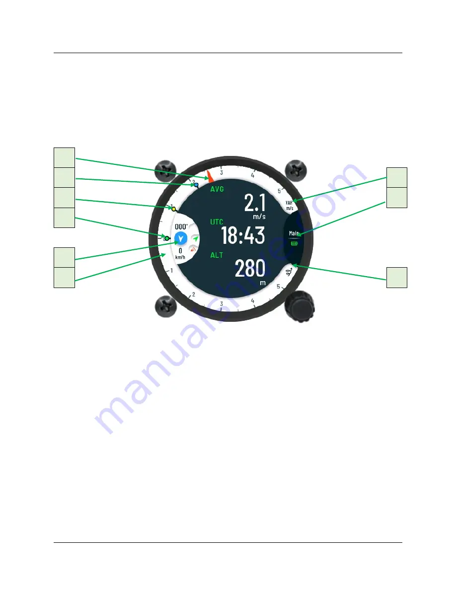
Main page displays all needed flight information. It can display up to three digital numeric
navbox information on main screen. 

Together with digital numeric information there is also wind indicator (direction and speed).

Additional, status displays BT connectivity, battery level, GPS reception and Flarm connectivity. 

1

Figure 2: Reference view of main page.

2

7

3

8

4

5

6

9

Description:

1.

Vario needle

BASIC AND ADVANCE

2.

Average vario indicator (blue circle)

BASIC AND ADVANCE

3.

MacCready setting indicator (yellow circle)

ADVANCE

4.

Thermal vario indicator (green circle)

 ADVANCE

5.

Wind, Flarm, GPS and BT module status

ADVANCE

6.

Vario scale

BASIC AND ADVANCE

7.

Vario scale units and type of needle (VAR – vario)

BASIC AND ADVANCE

8.

Battery status indicator with name of the page

BASIC AND ADVANCE

9.

Thermal mode icon

BASIC AND ADVANCE

12

Summary of Contents for FenixS advance

Page 1: ...FenixS User s manual for advance and basic version version 1 0 RC Electronics d o o September 2021...

Page 2: ...enixS user s manual Document Revision 1 0 September 2021 Contact Information Publisher and producer RC Electronics d o o Otemna 1c 3201 martno v Ro ni dolini Slovenia Email support rc electronics eu 1...

Page 3: ...S user s manual Document Revision 1 0 September 2021 Revision History The following table shows full description of changes made in this document DATE DESCRIPTION October 2021 Initial release of docum...

Page 4: ...oftware update 10 2 5 Device shutdown 11 2 5 1 Loss of main power during flight 11 3 Page overview 11 3 1 Main page 12 3 1 1 Digital numeric navigation information 13 3 1 2 Flight mode 14 3 1 3 Needle...

Page 5: ...info page 36 4 5 Logbook page 37 4 6 Flight statistic info page 38 4 7 Warnings 39 5 Rear of unit 40 5 1 Data port pinout 41 6 Bluetooth connectivity 42 6 1 Pairing 42 6 2 Supported data transfers 42...

Page 6: ...S user s manual Document Revision 1 0 September 2021 10 1 2 Set QNH 46 10 2 During flight 46 10 2 1 Set QNH 46 10 2 2 Wind calculation 46 10 2 3 Influence of wind in final glide 47 10 3 After landing...

Page 7: ...t features the pilot requires in the unit it can choose between basic and advance version of the unit Below is the short list of the FenixS functionality Display of GPS info Internal beeper for Flarm...

Page 8: ...p menu YES YES Volume control YES directly on knob YES via quick menu MC Ballast Bugs set NO YES via quick menu Speed to flay calculator NO YES Thermal Assistant NO YES needs external GPS source Flarm...

Page 9: ...any time For more additional info please visit our website https www rc electronics eu 2 Basic operation In the following section we will provide more details of the FenixS unit We will present you t...

Page 10: ...S user s manual Document Revision 1 0 September 2021 2 2 Front view Figure 1 Reference front view of device FenixS intro screen 2 1 3 1 Main round screen 2 Device version 3 Rotary knob with push funct...

Page 11: ...m exit from sub page or enable the pilot to customize navbox displayed data on main page BASIC VERSION Rotation will change vario volume Short press for confirmation entering to settings menu and conf...

Page 12: ...s an option If internal battery in installed then unit will continue with its operation Internal battery can maintain all FenixS functions for additional 30min 3 Page overview Each page was designed i...

Page 13: ...GPS reception and Flarm connectivity 1 Figure 2 Reference view of main page 2 7 3 8 4 5 6 9 Description 1 Vario needle BASIC AND ADVANCE 2 Average vario indicator blue circle BASIC AND ADVANCE 3 MacC...

Page 14: ...rea of the main screen is used to display digital numeric information The pilot can set up to three digital numeric values at the same time on the main screen 13 Figure 3 Displaying one information on...

Page 15: ...speed These values are represented graphically and numerically in a small half circle on the left side center of the main screen Wind indication features Wind direction pointer to show wind direction...

Page 16: ...Internal battery if integrated will be automatically charging during this mode Different color of indicator shows different current charge state of internal battery RED will indicate near empty batte...

Page 17: ...nal data Figure 11 Option for change navigational informational Figure 12 Main page ready for customization Once on main customization page first position of navbox data will be colored yellow This gi...

Page 18: ...ft Altitude Alt QNH ft Flight level Thermal gain Flarm alt Distance Tp Distance Apt Distance Tsk Distance Nrst Flarm dist Final glide Tp Final glide Apt Final glide Tsk Final glide Nrst TAS IAS Ground...

Page 19: ...u on main page Value can be then change by rotating the rotary knob in CW or CCW direction Every additional short press on the rotary knob will confirm last set value and jump to the next setting BASI...

Page 20: ...0 September 2021 Ballast setting Supported only in Advance version Figure 16 Ballast set view Bugs setting Supported only in Advance version Figure 17 Bugs set view QNH setting Supported on Basic and...

Page 21: ...FenixS user s manual Document Revision 1 0 September 2021 Brightness setting Supported on Basic and Advance version Figure 19 Brightness set view 20...

Page 22: ...e saved into internal device memory so they needs to be entered only once In the Advance version the pilot must rotate rotary knob to the Setup preview page In the Basic version to enter in the settin...

Page 23: ...ta port Units Localization Info Password BASIC VERSION Vario SC Units Localization Info Password 3 3 1 Pilot In the Pilot sub menu settings can be made for Weight Reserve 22 WARNING Due to the direct...

Page 24: ...o hear current frequency range and adjust it if needed Range lets the pilot adjust the current scale of selected vario unit In the case of kts numbers 5 10 or 20 can be set as scale The same principle...

Page 25: ...following settings can be made on indicators 24 Altitude Optional units o ft o m Climb rate Optional units o m s o m Speed Optional units o km h o mph o kts Wind speed Optional units o km h o mph o k...

Page 26: ...sub menu a list of different primary pages can be viewed The pilot can choose from list which pages will show or be hidden during device operation Sub menu includes following list of pages Thermal as...

Page 27: ...alerts which can be left disabled or enabled for use during a flight The Voice sub menu includes following settings Volume Range 0 to 100 Voice test To test audio level Flarm traffic Options o Enable...

Page 28: ...erties of glider type will be defined with variables in sub menu Polar A variable to set polar A parameter of glider Polar B variable to set polar B parameter of glider Polar C variable to set polar C...

Page 29: ...set in sub page Data port The pilot can set the following parameter Data port 2 parameter to set communication speed between the FenixS data port 2 and the externally connected device The following da...

Page 30: ...guage can be chosen between English and German Time zone for local time 3 3 9 Info Unique device identifiers can be seen in sub menu Info Displayed list shows following identifiers Serial nr serial nu...

Page 31: ...sion 1 0 September 2021 3 3 10 Password Special function passwords can be used 46486 will set FenixS to factory default state all settings are cleared and default are used 99999 will clear logbook 30...

Page 32: ...The displayed Thermal assistant page will show following information on main screen GAIN will display accumulated lost altitude from the very start of circling ALT will display current altitude of th...

Page 33: ...glider on the left side Off center the integrated airspeed can be seen as well as altitude To enter the Thermal assistant submenu the pilot must short press bottom rotary knob Thermal assistant submen...

Page 34: ...ch are higher brown the ones which are lower and white the ones which are the same altitude 20m Selected object is colored in yellow color Figure 32 Short press on bottom rotary knob will allow pilot...

Page 35: ...tails selecting will display all information of the currently selected glider If a glider with the unknown details is selected the pilot can manually insert parameters in the FenixS unit Parameters wi...

Page 36: ...lot must turn rotary knob CW to zoom in or CCW to zoom out With selected range the pilot must short press on the rotary knob to confirm this action 1 Figure 35 Reference view of the Take off page 2 3...

Page 37: ...on to the take off point DIST displays distance to the take off point 4 4 GPS info page Once on GPS info page following information can be seen Fix Quality Satellite number displaying receiving signal...

Page 38: ...en During this mode the pilot can access list of flights with a short press on the rotary knob With the displayed list of last 50 flights the pilot can scroll through the list by rotating the bottom r...

Page 39: ...ght statistic info page Once the flight starts the Logbook page will be change to the Flight statistic page with the following available data to view Takeoff displays time of take off Duration display...

Page 40: ...to an obstacle Red rhombus will indicate if for the nearby obstacle is higher or lower Figure 40 Obstacle warning view Traffic warning will indicate if aircraft is nearby The red direction symbol wil...

Page 41: ...ipheral connections 1 Figure 42 Reference rear view of the FenixS 2 3 4 Description 1 Pst TE pressure connections 2 Audio 3 5mm Mono output for speaker 3 Power 9 32 Vdc connector to connect external p...

Page 42: ...2021 5 1 Data port pinout Pin number Pin description 1 Power output same voltage as on power cable 9 32V 2 Not used 3 Not used 4 RS232 data input FenixS receives data 5 RS232 data output FenixS trans...

Page 43: ...XXXX represents serial number of the unit will be visible on detected list when in range and turned on Pair code will be requested to start communication with PDA PNA and FenixS Just confirm the pair...

Page 44: ...cal properties Dimensions 65mm x 62mm x 30mm Weight 120g 7 1 Electrical properties POWER USAGES Input voltage 9V Vdc to 32V Vdc Input current 80mA 13V Vdc AUDIO POWER DELIVERY Output power 1W RMS 8 DA...

Page 45: ...nut for rotary switches Place the unit in the instrumental panel and first screw in the two black screws and then mounting nuts for rotary switches After that put back the knob on the rotary switch Do...

Page 46: ...takeoff the unit will start recording It is recommended to switch the unit on a few minutes before takeoff After landing the unit will close the flight after approximately 20 seconds at standstill so...

Page 47: ...10 2 During flight The unit hardware and firmware concept are so far optimized that the pilot doesn t spend too much time to operate the unit during flight A very significant indication that shows tha...

Page 48: ...of wind in final glide The actual wind data speed and direction influences the final glide calculation 10 3 After landing It is recommended to keep the instrument on for a few minutes after landing s...

Reviews: