A8 Overview 38
Table 25. Rear View of A8
1
PCIe expansion card slots
2
PCIe expansion card slots
3
PCIe expansion card slots
4
PCIe expansion card slots
5
Power supply (x2)
6
Network connectors (x4)
7
USB 3.0 connectors (x2)
8
VGA connector
9
Serial connector
10
iDRAC9 Enterprise Network connector
11 System identification connector
12
System identification button
Drive Indicator Codes
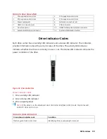
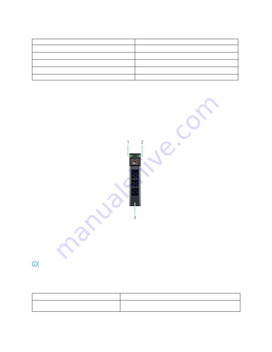
Each drive carrier has an activity LED indicator and a status LED indicator. The indicators
provide information about the current status of the drive. The activity LED indicator
indicates whether the drive is currently in use or not. The status LED indicator indicates the
power condition of the drive.
Figure 34. Drive indicators
Drive indicator codes
1.
Drive activity LED indicator
2.
Drive status LED indicator
3.
Drive capacity label
NOTE:
If the drive is in the Advanced Host Controller Interface (AHCI) mode, the status LED
indicator does not turn on.
Table 26. Drive indicators
Drive status indicator code
Condition
Flashes green twice per second
Identifying drive or preparing for removal.
Summary of Contents for V8
Page 1: ...rcgs20200916 2020 2020 2020 2020 2020 2020 2020 2020 2020...
Page 27: ...V12 Overview 26 Figure 21 Service Information with System Touch Points...
Page 75: ...RAID Storage 74 Select Virtual Disk Management Figure 63 PERC Adapter Server Profile View...
Page 81: ...RAID Storage 80 Select Create Virtual Disk Figure 69 Create Virtual Disk...
Page 82: ...RAID Storage 81 Select RAID level Figure 70 Select RAID Type...
Page 83: ...RAID Storage 82 Select Physical Disks Figure 71 Select Physical Disks...
Page 85: ...RAID Storage 84 Scroll up and Click Apply Changes Figure 73 Apply Changes...
Page 86: ...RAID Storage 85 Select OK Figure 74 Confirm Completion...
Page 89: ...RAID Storage 88 Confirm and Click Yes Figure 77 Confirm Operation...
Page 96: ...RAID Storage 95 Verify all settings and if correct click Finish Figure 84 Complete the Wizard...


