V1.0 Shanghai Empower Technologies Co., Ltd. © Copy Right
www.empower.cn
BM111 SERIES 3KW Auto-Focusing Laser Cutting Heads User Manual
9 | 28
3
Mechanical
Installation
3.1
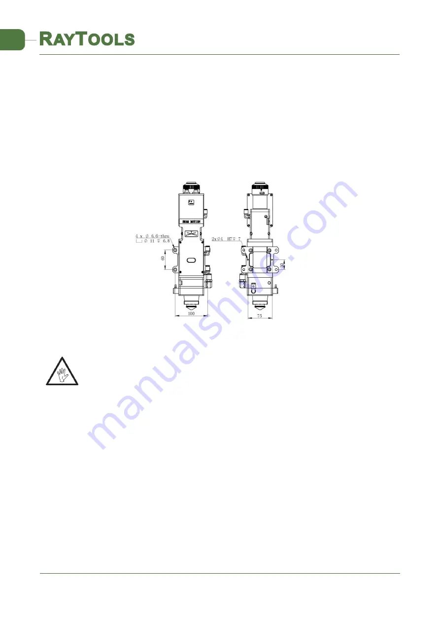
Mounting Holes
The mounting holes size and position of the BM111 laser
cutting head are shown in Figure 3.1,
which can be used to fix the laser head and machine tool. We strongly recommend customers to
install the laser head perpendicular to the process material surface as requested and make sure the
laser head is locked, this is one of the preconditions to ensure the follow-up stable cutting effect.
Note:
The Z-axis motor slide plate for fixing the laser cutting head should be connected with
machine tools and make sure there is a good grounding.
3.2
Connection of Water Pipe and Gas Pipe
3.2.1
Water-cooled interface
BM111 laser cutting head has 2 sets of water-cooled channels, the direction of water entry and
exit can be arranged arbitrarily. It is important to note that when the laser power is greater than 500
watt, we recommend users to use water-cooled. As you can see from Figure 3.2, the position and
quantity of the water interfaces, and the table below details the recommended water flow rate.
The design of this water-cooled interface is closed loop water-cooled system, and it also can be
Fig 3.1 -
mounting holes
position


