40
5. CONTROLS
Sequence of Operation
1. Upon initial application of 24VAC power, by toggling
the rocker switch to the “IDLE” position the PIM resets
with all outputs in the “OFF” state.
2.
Enabling the unit by toggling the third position (RUN)
of the rocker switch, allows the PIM and VERSA IC to
perform a processor and memory self-test to ensure
proper operation.
3. The PIM confirms the presence of a valid ID card
which matches the configuration stored in memory at
the factory. If a valid ID card is NOT present, the PIM
generates a diagnostic fault (ID Card Fault) and will
shut down waiting for this fault to be addressed.
4. The PIM reads the DIP switch settings and configures
itself for the desired operation. PIM DIP 3 = OFF
indicates primary-only pipe configuration, which uses
an Isolation valve, while PIM DIP 3 = ON means
primary / secondary and uses a heater pump.
5. The PIM scans the Ft_bus communications for the
VERSA board and if found, system operation is
controlled by the VERSA board. If the PIM does not
find the VERSA board, it will enter "limp-along" mode.
See Section 11 of the VERSA IC Manual (5000.72).
6. Non-volatile memory is checked for any active lockout
conditions. If any exist, they must be addressed
before the PIM will allow a new trial for ignition to
start.
7. The PIM continually monitors the flame status to
ensure that no flame is present during standby. If an
erroneous flame is detected, the PIM generates a
False Flame error fault.
8. The PIM verifies that the vent sensor is below the
vent limit temperature before burner operation. The
control uses the input from this sensor to automatically
reduce firing rate should the vent temperature
approach the vent material temperature limits. If the
vent temperature is exceeded, the PIM performs a
Post-purge and proceeds to a hard lockout (manual
reset).
9. A call-for-heat is initiated by the presence of any one
or more of the sources below. See
Figure 26.
a.
A heat demand (contact closure) on the Enable/
Disable field wiring terminals (#11 and #12)
b. A voltage greater than 1.0 VDC on the analog
0-10 VDC EMS signal input
(#13 and #14)
c. A heat demand present on the indirect DHW field
wiring terminals
(#4 and #5)
d. A heat demand from the VERSA board based on
the DHW sensor temperature
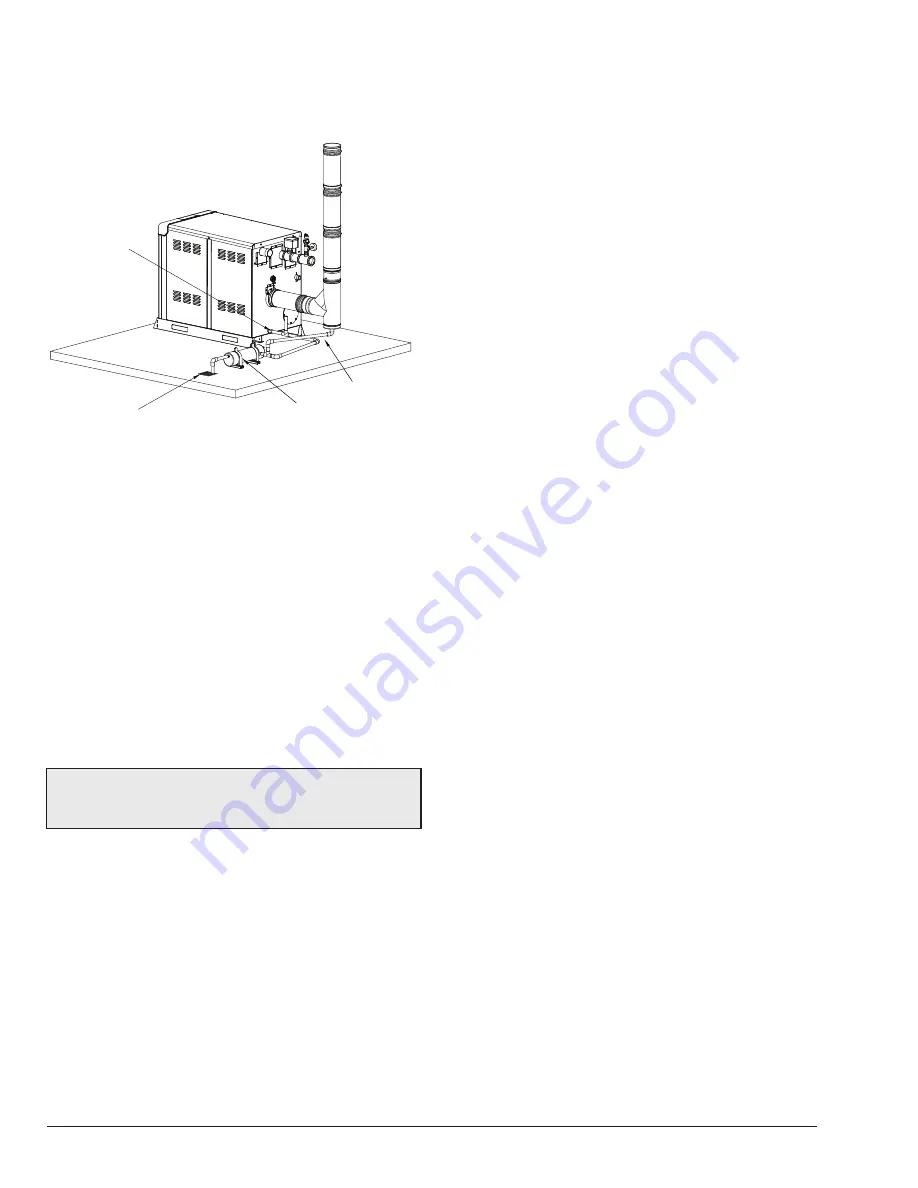
Figure 42
is a visual guide only. Follow the manufacturer’s
instructions for the installation of the Condensate Treatment
Kit and condensate drains.
CONDENSATE DRAIN
FROM VENT
Z-12
CONDENSATE
TREATMENT
CONDENSATE DRAIN
FROM UNIT
DRAIN
F10616
Figure 42. Visual Guide for Condensate Piping
Freeze Protection
To enable freeze protection, DIP switch position 7 (on the
PIM) must be turned on (UP position). This is the default
position.
If the water temperature drops below 45˚F (7ºC) on the
Outlet or Inlet sensors, the heater pump/isolation valve
is enabled. The heater pump is turned off/isolation valve
closed when both the Inlet and Outlet temperatures rise
above 50˚F (10ºC).
If either the Outlet or Inlet temperature drops below 38°F
(3ºC), the VERSA starts the burner at the minimum firing
rate. The burner cycle will terminate when both the Inlet
and Outlet temperatures rise above 42°F (6ºC).
NOTE:
Failure of the optional flow meter, if present, will
not initiate a heating cycle if temperatures drop below
38
°
F (3
°
C).
Summary of Contents for Xfiire 1000B
Page 54: ...54 6 WIRING DIAGRAM For a full size drawing visit www raypak com ...
Page 70: ...70 NOTES ...
Page 71: ...71 NOTES ...


