background image


HOW YOUR WATER HEATER WORKS 

 
The water heater consists of a gas burner, a combustion chamber lined with refractory tiles and a heat-exchanger 
made of finned copper tubes. Hot flue gases from the burner pass between the fins on the heat exchanger tubes 
and heat is transferred first to the fins and then by conduction into the water. Baffles are placed between the tubes 
to  control  the  flow  of  the  hot  flue  gases  and  ensure  efficient  operation  of  the  water  heater.  The  refractory  tiles 
insulate the combustion chamber to minimise loss of heat and protect the surroundings from the temperature of the 
burner  flames.  The  gas  supply  to  the  burner  is  controlled  by  a  thermostat,  which  senses  the  temperature  of  the 
water. 

Automatic safety controls are fitted to the water heater: 


to ensure safe ignition of the gas whenever there is a call for heating; 


to continuously monitor the burner flame; and 


to prevent excessive temperatures or pressures in the water system. 
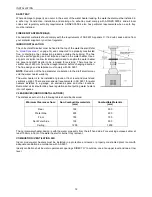
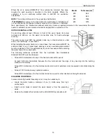
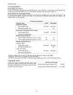
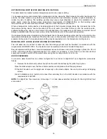
MAINS PRESSURE 

In  water  heating  applications,  the  water  heater  is  designed  to  operate  in  conjunction  with  one  or  more  hot  water 
storage tanks, which would be connected directly to the mains  water supply. If the mains supply pressure in your 
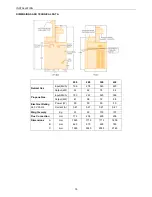
area  exceeds  the  value  shown  in  the  table  on  page 14  or  the  maximum  inlet  pressure  for  the  storage  tanks,  a 
pressure limiting valve must be fitted. 

In mechanical and process heating applications, the system pressure must not exceed the value shown in the table 
on page 14. 

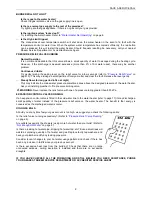
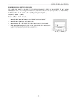
ELECTRONIC THERMOSTAT (ON/OFF MODELS) 

On/Off models are fitted with an electronic thermostat that operates the gas control by switching its power on and 
off, so a constant temperature is maintained. The thermostat is mounted  on the control panel of the water  heater 
and the protective over temperature cut out is mounted inside the lower front cover of the water heater. 

There  is  no  need  to  switch  the  water  heater  off  when  it  is  not  in  use.  The  thermostat  is  fully  automatic  and  only 
allows  the  gas  control  to  ope

n  when  the  burner  requires  gas  for  heating.  The  thermostat may  flash  “AH”  (alarm 

high) and the current water temperature, or “AL” (alarm low) and the current water temperature. This is not a cause 
for concern unless the temperature displayed  is more than 1

0ºC above the set temperature. Refer to “

Diagnostic 

Features of Electronic Thermostat

” on page 8. To adjust the thermostat settings refer to “

Temperature Control

” on 

page 30. 

MECHANICAL CONTROL (MODULATING MODELS) 

Modulating  models  are  fitted  with  a  mechanical  modulating  gas  control  that  varies  the  gas  flow  to  the  burner  in 
order  to  maintain  a  constant  temperature.  The  temperature  adjustment  is  on  the  body  of  the  modulating  control, 
mounted inside the lower front cover of the water heater. The protective over temperature cut out is also mounted 
inside the lower front cover of the water heater. 

To adjust the thermostat setting refer to “

Temperature Control

” on page 33. 

BURNER IGNITION 

The water heater incorporates an automatic burner ignition system, incorporating an automatic pilot burner, which 
lights the main burner gas when the thermostat registers a need for heating. 

On/Off models have a hot surface igniter (HSI) that heats up when there is a call for heating. When the HSI probe 
is  up  to  temperature,  a  valve  opens  allowing  gas  to  the  pilot  burner  and  this  is  ignited  by  the  HSI  probe.  When 
successful ignition of the pilot flame is detected, the valves open to supply gas to the main burner. If the pilot fails 
to ignite after two attempts, the ignition system will lock out. 

Modulating models have a spark generator that begins operating when  power is applied and any external controls 
call  for  the  water  heater  to  operate.  At  the  same  time  a  valve  opens  to  supply  gas  to  the  pilot  burner.  After 
successful  ignition  of  the  pilot  flame  has  been  detected,  the  valves  open  to supply  gas  to the  main  burner,  when 
there is a call for heating. If the pilot fails to ignite within 15 seconds, the ignition system will lock out. 


Summary of Contents for B0200

Page 1: ...stallation Instructions Raypak Water Heaters Models Types B0200 NCO NCM PCO PCM B0280 B0350 B0430 This water heater must be installed and serviced by a qualified person Please leave this guide with a...

Page 2: ...to install this water heater and ask for your Compliance Certificate Warning Upon completion of the installation and commissioning of the water heater leave this guide with the householder or a respo...

Page 3: ...terest CONTENTS 3 ABOUT YOUR WATER HEATER 4 HOW YOUR WATER HEATER WORKS 7 SAVE A SERVICE CALL 8 REGULAR CARE 10 INSTALLATION 11 CONNECTIONS PLUMBING 17 CONNECTIONS ELECTRICAL 20 LOCATION OF CONTROLS 2...

Page 4: ...uitable for the application and will not cause scald injury We recommend and it may be required by regulations that an approved temperature limiting device be fitted into the hot water piping to the b...

Page 5: ...Propane model A Propane model is designed to operate on Propane only The use of Propane Butane mixture such as automotive LPG fuel in a Propane model is unsafe and can cause damage to the water heater...

Page 6: ...ribed on pages 35 HOW LONG WILL THE WATER HEATER LAST The water heater is supported by a manufacturer s warranty refer to page 39 There are a number of factors that will affect the length of service t...

Page 7: ...er heater off when it is not in use The thermostat is fully automatic and only allows the gas control to open when the burner requires gas for heating The thermostat may flash AH alarm high and the cu...

Page 8: ...valve to each shower outlet to reduce water usage Pressure relief valve running Is the relief valve discharging too much water Refer to Pressure Relief Valve Running on page 9 Thermostat setting Ensu...

Page 9: ...indicate the mains water pressure sometimes rises above the designed pressure of the water heater Ask your installing plumber to fit a pressure limiting valve WARNING Never replace the relief valve w...

Page 10: ...failing Warning Exercise care to avoid any splashing of water as water discharged from the drain line will be hot Stand clear of the drain line s point of discharge when operating the valve s lever If...

Page 11: ...ure relief valve may be supplied inside the water heater casing This kit must be removed before the water heater is operated READ THESE INSTRUCTIONS IN FULL INSPECTION OF EQUIPMENT Check the water hea...

Page 12: ...ght diverter before changing direction The flue design and installation must comply with AS 5601 NOTE Reduction of the flue diameter or alteration to the draft diverter may void the water heater warra...

Page 13: ...ase the base material MUST be solid and filled in e g if steel mesh decking is used a suitable plate material must be installed to fill in the perforations to prevent excessive drafts entering the wat...

Page 14: ...ng kPa 700 550 700 550 Mechanical Heating kPa Minimum Supply Pressure System water temperatures up to 65 C kPa 70 70 System water temperatures above 65 C kPa 120 120 Maximum Supply Pressure with ECV f...

Page 15: ...nches off before this valve or from another cold water line in the premises then a pressure limiting valve of an equal pressure setting may be required prior to the temperature limiting device REDUCIN...

Page 16: ...ut kW 44 62 76 94 Propane Gas Input MJ h 185 261 323 396 Output kW 41 58 72 88 Electrical Rating 240 V 50 Hz Power W 50 50 50 50 Current A 0 21 0 21 0 21 0 21 Weight empty Kg 91 93 103 107 Flue Connec...

Page 17: ...pipe work size and water heater water connections without allowing for friction loss which will occur Low water flow will cause damage to the water heater and system components GAS INLET The gas conne...

Page 18: ...g to the connection on the inlet outlet header then screw the relief valve onto the other end of the elbow Seal the treads using Teflon tape never hemp A drain line must be installed in accordance wit...

Page 19: ...stem should be provided with manual bleed points or fitted with automatic air vents The design of the system must be such that the water heater is provided with adequate water flow and pressure at all...

Page 20: ...hermostat setting requirements with the householder or responsible officer Refer to Temperature Control on page 30 INTERMITTENT PUMP OPERATION For applications utilising intermittent pump operation an...

Page 21: ...On Off models cannot be connected to a building management system CONTROL PANEL ACCESS To access the electrical enclosure Remove the Philips head screw from the bottom of the front panel Remove the fr...

Page 22: ...CONNECTIONS ELECTRICAL 22 WIRING DIAGRAM ON OFF MODELS...

Page 23: ...CONNECTIONS ELECTRICAL 23 WIRING DIAGRAM MODULATING MODELS...

Page 24: ...PTION MECHANICAL HEATING SYSTEMS NOTE When connecting additional controls the relays and timers etc must be located in an additional enclosure NOT fitted within the water heater For outdoor installati...

Page 25: ...ff type water heaters are fitted with a Honeywell SV9605 smart valve This gas control incorporates the ignition electronics and provides the gas supply to the pilot and main burners Modulating Models...

Page 26: ...loose fitting long sleeved clothing or disposable overalls Wear gloves and eye protection Consult Occupational Health and Safety Authorities for any further information AFTER HANDLING Rinse any expos...

Page 27: ...sure that the main gas isolation valve is closed OPERATIONAL CHECKS Turn on the water heater and circulation pump and verify the flow switch operation if fitted refer to To Turn on the Water Heater on...

Page 28: ...at the inlet to the water heater Plug in the power supply cord at the power outlet Switch on the electrical supply at the power outlet to the water heater NOTE If the water heater is correctly instal...

Page 29: ...label refer to Location of Controls on page 25 Turn off the water heater Replace the cap on the pressure regulator adjuster Disconnect the manometer and replace the pressure tap screw and washer Chec...

Page 30: ...ach folder indicated by the relevant label just press the SET key once You can now scroll through the contents of each folder modify it or use its functions If you do not use the keyboard for over 15...

Page 31: ...TEMPERATURE CONTROL 31...

Page 32: ...at Cool mode HC H C H Ont Oft Delay time relay on dOn sec 0 250 0 Delay time relay off dOF min 0 250 0 dbi min 0 250 0 Delay time at start up OdO min 0 250 0 dis Key pad lock LOC y n n Password PA1 nu...

Page 33: ...d in a well pocket fitted in the outlet header and senses the temperature of the water leaving the water heater The high limit temperature setting is adjusted by removing the front cover loosen one Ph...

Page 34: ...ilot flame Yellow flames indicate some restriction of the combustion air openings or incorrect burner gas pressure setting A bright orange luminous flame is not normal and can cause sooting under prol...

Page 35: ...elief valve In a scaling water supply calcium carbonate is deposited out of the water onto any hot metallic surface Where the saturation index exceeds 0 80 warranty does not apply to a copper heat exc...

Page 36: ...36 This page is intentionally blank...

Page 37: ...37 This page is intentionally blank...

Page 38: ...38 This page is intentionally blank...

Page 39: ...led site shall be the owner s responsibility 2 5 Where the water heater is installed in a position that does not allow safe or ready access the cost of that access including the cost of additional mat...

Page 40: ...ish to make a claim under this warranty you need to a Contact Rheem on 131031 and provide owner s details address of the water heater a contact number and date of installation of the water heater or i...

Reviews: