background image

3. INSTALLATION PROCEDURES.

CODE  REQUIREMENTS

Installation must be in accordance with local codes, or in the absence of local codes with the latest edition

of the National Fuel Gas Code, 

ANSI Z223.1, 

 the National Electrical Code, 

ANSI/NFPA 70.  For Canada, CAN/

CGA B149.1 and .2, and CSA C22.2 No. 1.

LEG INSTALLATION

Four (4) legs are supplied loose within the carton for installation at the site.  This will provide the required six-

inch clearance off the floor.  To install the legs, raise one end of the heater just high enough to allow the legs to
be screwed into the two corners of that end.  Make sure each leg is tightened securely by hand.    Lower the heater
gently to minimize any undue strain on the two (2) legs.  Gently raise the other end, and repeat the same procedure
for the other  two (2) legs.  Rotate the lower section of each leg as necessary to level the heater in place.

Booster water heater should not be located in an area where water leakage will result in damage to the area

adjacent to it or to lower floors of the structure.  Where such areas cannot be avoided, it is recommended that
a suitable catch pan, adequately drained, be installed under this heater. Do not install directly on carpeting.

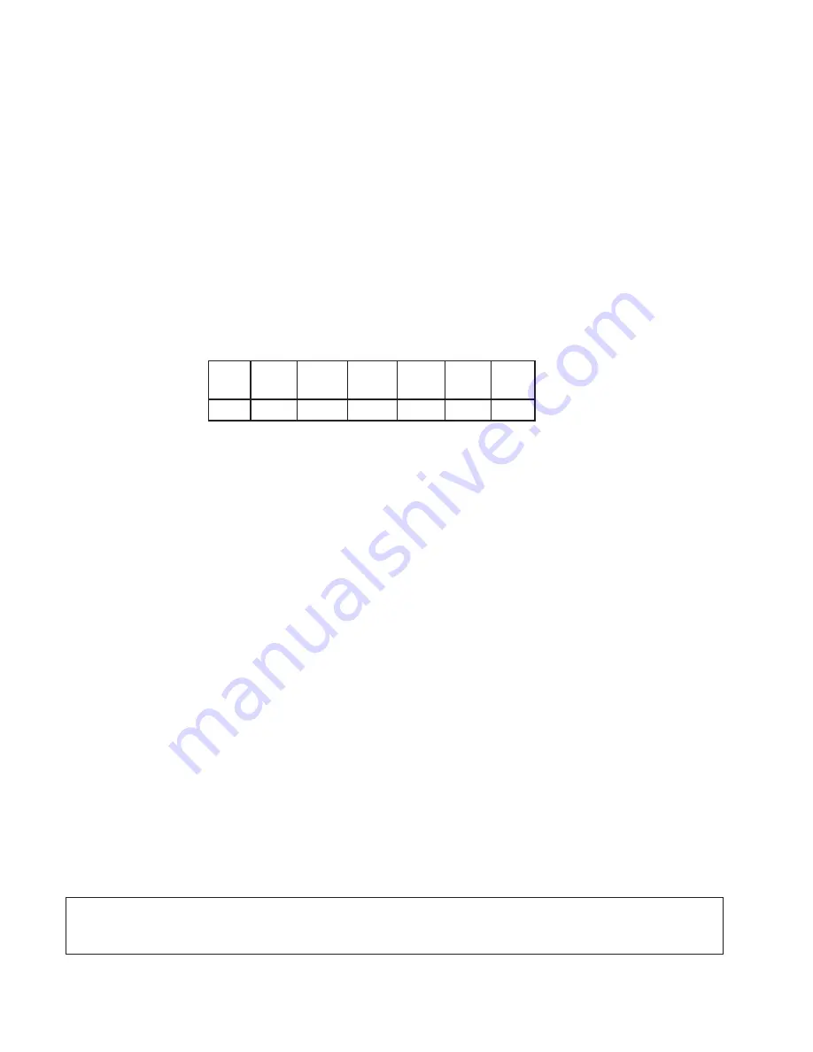
CLEARANCE REQUIREMENTS

Floor

Top

Left

Right

Front

Back

Vent

Side

Side

   *

  0"

  6"

  6"       Alcove   6"

  1"

*Approved  for installation on combustible flooring.

A front clearance of at least 24" is recommended for adequate service of burner-tray and controls.

COMBUSTION/VENTILATION AIR

B195 COMBUSTION AIR ADJUSTMENT

This model is equipped with an air adjustment screw on the combustion air blower inlet.  For natural gas the

opening is factory set at about 2.12" diagonal dimension, for propane gas the opening is 1.875" diagonal
dimension,  which should be the proper setting for most installations.  However, field conditions including unusual
gas characteristics may create a need for adjustment to achieve optimum performance.  When the combustion
air setting is proper, there will be some lifting of the flames on some areas of the burner tile under cold start
conditions.  After about five minutes of operation, the flames should settle down and blue tips should become
visible on some areas and orange glow on other sections of the burner tile.  Lifting of flames beyond five minutes
would indicate too much combustion air.  The adjustment screw should be turned clockwise to reduce the
combustion air supply until the lifting settles down.  If the blue tips disappear and the entire burner surface
becomes radiant white, it indicates that there is not enough combustion air and the adjustment screw should be
turned counterclockwise to increase the combustion air opening until the blue tips and orange glow become
visible again.

The optimum excess air will result in CO

2

 levels between 8 and 8.5% for natural gas and 9.2 to 9.7% for

propane.  If a flue gas analyzing equipment is available, the opening can be adjusted to achieve this CO

2

 level.

Or, if an inclined manometer is available, pressure measured at the combustion air switch pressure tap, can be
set at -0.35" W.C. for natural gas and -0.60" W.C. for propane by means of the adjustment screw.  Pressure at
this level will result in the proper CO

2

 levels mentioned above.

Again, the factory setting will be adequate for most field conditions and adjustment will not normally be

required.

CAUTION:

 A dusty kitchen environment combined with greasy laden air will clog the combustion air blower wheel

and cause premature failure of the heater.  Combustion air must not be contaminated by corrosive chemical
fumes which can severely damage the heater.

4

Summary of Contents for B-195

Page 1: ...cause property damage personal injury or loss of life Refer to this manual Installation and service must be performed by a qualified installer service agency or the gas supplier This manual should be...

Page 2: ...UNIT 16 Trouble Shooting Guide Maintenance 18 6 PARTS 19 Illustrated Parts 20 Parts List 23 WARRANTY These instructions are provided to assure the proper installation operation and maintenance of the...

Page 3: ...installing your Raypak Heater If there are any questions which this manual does not answer please contact your local Raypak Representative 2 GENERAL SPECIFICATIONS The Raypak Booster Heater is design...

Page 4: ...is 1 875 diagonal dimension which should be the proper setting for most installations However field conditions including unusual gas characteristics may create a need for adjustment to achieve optimu...

Page 5: ...This can be done easily in the field Remove the top casing cover to gain access to the flue collector box Remove the screws along the sides of the flue collector Disconnect the vent switch tubing from...

Page 6: ...6 Fig 8975 3 Applies only to exhaust hood over cooking equipment...

Page 7: ...cated not less than seven feet above grade when it is adjacent to public walkways 3 The bottom of the vent terminal shall be located at least twelve inches above grade or ground or normally expected s...

Page 8: ...shwasher lines Adjust setting to maintain 20 PSI at the dishwasher Install a suitable water hammer arrester be tweentheboosterheateranddishwasher asshown on page 10 typical piping The heater and its g...

Page 9: ...lier or the local plumbing inspector on how to correct this situation DO NOT plug the relief valve or install a shut off valve in the discharge drain line The heater is equipped with a circulator to p...

Page 10: ...d for the heater to operate properly Consult wiring diagram Provide a separate fused circuit from the main electrical panel to the heater and a disconnecting means within sight of the heater Remove th...

Page 11: ...Turn off electrical power to boost heater before servicing any component in the heater to prevent equipment damage or personal injury NOTE If it is necessary to replace any of the original wiring it...

Page 12: ...f after third cycle ignition is not proven the module will go into lockout and a Red LED will start blinking To recycle the burner momentarily turn the power switch to the off position and then to the...

Page 13: ...cian to inspect the heater and to replace any part of the control system and gas control which has been underwater HOT SURFACE IGNITION MODELS WITH ROBERTSHAW GAS VALVE 1 STOP Read the safety informat...

Page 14: ...very six months Refer to the Servic ing Section related to burner removal BURNER INSPECTION VISUAL 1 Shut off electrical power and gas supply to the heater 2 Disconnect wiring to hot surface ignitor a...

Page 15: ...mit control e Reverse above steps to reinstall 9 Air Vent Switch Replacement a Shut off electrical power to the heater b Remove front panel c Remove wiring connections to switch d Remove screws 2 hold...

Page 16: ...0 67 0 78 amps re move and inspect impeller 2b Replace cartridge or entire pump as needed 2c Clean and inspect blower wheel Check operation Replace blower if needed 3a If Red LED on circuit board is O...

Page 17: ...ections inside control box 4b Check all connections and wire nuts 4c Check wire connection to remote sen sor 4d Check gas pressure at outlet of valve under load pressure should be 3 5 in W C for Natur...

Page 18: ...ndard company warranties must be properly tagged with RAYPAK return parts tag completely filled in with the heater Serial Number Model Number etc and shipped to the Company freight prepaid If determin...

Page 19: ...19...

Page 20: ...20...

Page 21: ...21...

Page 22: ...ny failed part during the first 90 days of this Warranty will be paid by Raypak Service must be performed by a recognized and certified service agency during normal working hours All other costs are e...

Page 23: ...c 2151 Eastman Avenue Westlake Village CA 93030 805 278 5300 FAX 800 872 9725 Raypak Canada Limited 2805 Slough St Mississauga Ontario Canada L4T 1G2 416 677 7999 FAX 416 677 8036 Litho in U S A www r...

Reviews: