3.6 Grounding
These grounding requirements are applicable for Raymarine
equipment with a dedicated ground terminal.
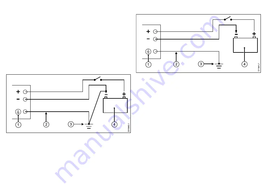
• The ground terminal must be connected to a common ground
point.
• It is recommended that the common ground point is a bonded
ground, i.e. with the ground point connected to battery negative,
and situated as close as possible to the battery negative terminal.
If a bonded ground system is not possible, a non-bonded RF
ground may be used.
Bonded ground system (preferred)
D
1
1
9
4
0
-1
2
4
3
1
RF ground system (alternative)
D
1
1
9
4
1
-1
2
4
3
1
1.
Ground terminal. (This may also be labelled as Ground, or
Screen.)
2.
Ground braid.
3.
Bonded (preferred) or non-bonded RF ground.
4.
Power supply or battery.
Implementation
If several items require grounding, they may first be connected
to a single local point (e.g. within a switch panel), with this point
connected via a single, appropriately-rated conductor, to the boat’s
common ground. The preferred minimum requirement for the path
to ground (bonded or non-bonded) is via a flat tinned copper braid,
with a 30 A rating (1/4 inch) or greater. If this is not possible, an
equivalent stranded wire conductor maybe used, rated as follows:
• for runs of <1 m (3 ft), use 6 mm
2
(#10 AWG) or greater.
• for runs of >1 m (3 ft), use 8 mm
2
(#8 AWG) or greater.
In any grounding system, always keep the length of connecting
braid or wires as short as possible.
28
SPX SmartPilot installation instructions
Summary of Contents for SmartPilot SPX-10
Page 1: ......
Page 2: ......
Page 4: ......
Page 6: ...6 SPX SmartPilot installation instructions ...
Page 10: ...10 SPX SmartPilot installation instructions ...
Page 40: ...40 SPX SmartPilot installation instructions ...
Page 44: ...44 SPX SmartPilot installation instructions ...
Page 49: ......
Page 50: ...www raymarine com ...


