background image

10

SmartPilot Series Commissioning Guide

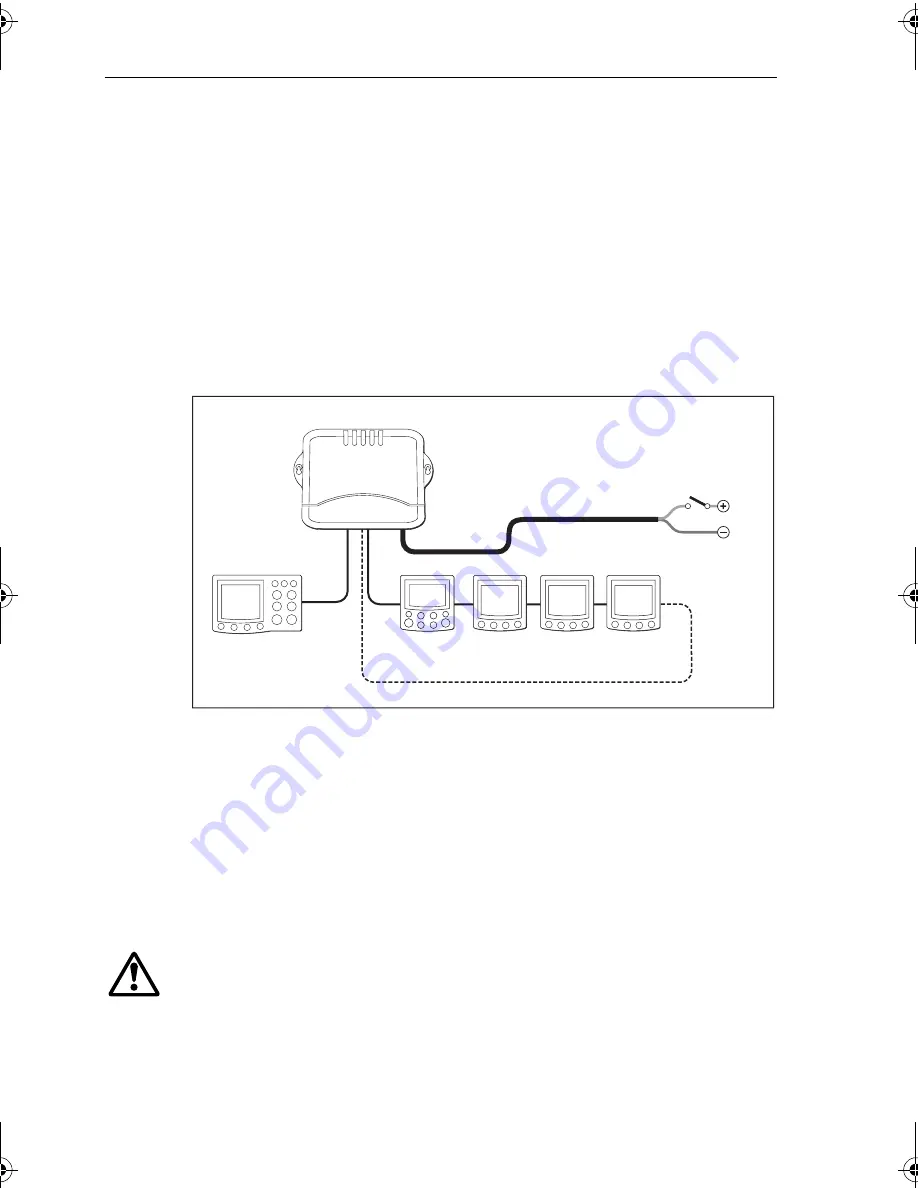
Isolated control unit, single power supply (S2 and S3 
computers only)

If you have two control units, we recommend that you connect one to each 
SeaTalk terminal. In the following illustration: 
• the SmartPilot computer provides power to the SeaTalk system
• one control unit is connected on its own to SeaTalk A so it is isolated against 

any possible failure of SeaTalk B

If the SeaTalk B line fails, the isolated control unit will switch to Standby mode as 
a safety measure. By pressing 

auto

 on the isolated control unit you can regain full 

autopilot control.


Note:  

Depending on the number of SeaTalk units and the total length of SeaTalk cabling, 

you may need to provide12 V power supply to each end of the SeaTalk bus (‘ring-main’ 
style). Refer to the instrument handbook for more information.

Separate SmartPilot computer and instrument power

Another option is to provide separate power supplies to the SmartPilot computer 
and SeaTalk system so you can have independent, switched instrument and pilot 
systems. 

Note:  

DO NOT connect the SeaTalk RED wire at the SmartPilot terminal

WARNING:  Use correct fuse

The fuse supplying the instrument system MUST be rated at 5A or 
less.

The behavior of the computer and the instruments now depend on where power 
is applied to the system.

Course computer
power supply
(via breaker/fuse)

Isolated control unit, single power supply

Second

control unit

Isolated

control unit

D6383-1

ST60 instruments

SeaTalk B

SeaTalk A

SeaTalk bus

Extra connection on larger SeaTalk systems

SmartPilot
computer

81273_1.book  Page 10  Thursday, November 10, 2005  8:25 AM

Summary of Contents for SmartPilot Series

Page 1: ...SmartPilot Series Commissioning Guide Document reference 81273 1 Date Date December 2005 ...

Page 2: ...SailPilot SeaTalk and SportPilot are registered trademarks of Raymarine Ltd Raymarine SmartPilot AST Advanced Steering Technology AutoAdapt AutoLearn AutoRelease AutoSeastate AutoTack AutoTrim FastTrim GyroPlus RayGyro RayPilot and WindTrim are trademarks of Raymarine Ltd ...

Page 3: ... this handy guide to the main operations SmartPilotOperatingGuide Detailedoperatinginformationaboutyour SmartPilot Note This handbookcontains importantinformationabouttheinstallationandcommis sioningofyournewRaymarineproduct Atthebackthereisanindexandglossaryofterms Togetthebestfrom the productpleaseread this handbookthoroughly SmartPilot Controller Compatibility This handbook allows you to commis...

Page 4: ...ING Calibration requirement We supply this product calibrated to default settings that should provide initial stable performance for most boats To ensure optimum performance on your boat you must complete Chapter 2 WARNING Navigation aid Although we have designed this product to be accurate and reliable many factors can affect its performance As a result it should only be used as an aid to navigat...

Page 5: ...t they will perform under all conditions it is important to understand what factors could affect the operation of the product TheguidelinesgivenheredescribetheconditionsforoptimumEMCperformance butitisrecognizedthatitmaynotbepossibletomeetalloftheseconditionsinall situations ToensurethebestpossibleconditionsforEMCperformancewithinthe constraints imposed by any location always ensure the maximum se...

Page 6: ...s used with Raymarine equipment Always use the ferrites supplied by Raymarine Connections to other equipment IfyourRaymarineequipmentistobeconnectedtootherequipmentusingacable notsuppliedbyRaymarine a suppressionferriteMUSTalwaysbeattachedtothe cable near to the Raymarine unit Handbook information Tothebestofourknowledge theinformationinthishandbookwascorrectwhen it went to press However Raymarine...

Page 7: ...es 4 1 4 Connecting the Power and the Drive unit 5 Grounding the SmartPilot 7 1 5 Fuse Protection 8 1 6 How to connect SmartPilot system elements 8 Securing the Cables 9 1 7 How to connect SeaTalk equipment 9 Single control unit single power supply 9 Isolated control unit single power supply S2 and S3 computers only 10 Separate SmartPilot computer and instrument power 10 WARNING Use correct fuse 1...

Page 8: ...ument connections 21 Step 3 Check the autopilot operating sense 21 Check the rudder position sensor 21 Check the autopilot steering sense 22 Step 4 Adjust key SmartPilot settings 22 Enter Dealer Calibration mode 23 Set the vessel type 23 Set the drive type 25 Align the rudder position sensor 26 Set the rudder limits 26 Save the new settings 26 2 2 Seatrial Calibration 27 Seatrial safety 27 Calibra...

Page 9: ...45 Accessing Dealer Calibration 45 Dealer Calibration screens and settings 47 SeaTrial Calibration lock 47 Vessel type 47 Drive type 48 Align rudder 48 Rudder limit 49 Rudder gain 49 Counter rudder 49 Rudder damping 50 AutoTrim 50 Response level 51 Turn rate limit 51 Off course warning angle 52 Joystick mode PWR STEER 52 AutoRelease I O drives only 53 AutoTack angle 53 Gybe inhibit 53 Wind selecti...

Page 10: ...59 4 1 Fault finding 59 SmartPilot alarm messages 60 4 2 Maintenance 62 EMC servicing and safety guidelines 62 Product support 63 World wide web 63 Telephone help line 63 Help us to help you 63 SmartPilot Specifications 65 WARNING Potential ignition source 66 Glossary 67 Index 69 ...

Page 11: ...tPilot Computer S1 S1G S2 S2G S3 S3G SmartPilot Controller ST6001 ST6002 ST7001 ST7002 ST8001 or ST8002 Drive Unit Note ForVolvoPenta IPS autopilot systemsthe rudder referenceanddriveunits are not required Formoreinformation please refer tothe Connections guidesupplied with the DPU The remainder of this chapter covers the connection of these units When complete the core system will be connected li...

Page 12: ...eather and sailing conditions Non G systems do not contain a built in Gyro These can be upgraded with a dealer fitted internal Gyro or connecting an external Gyro unit SmartPilot Version Supply voltage Drive unit compatibility Built in Gyro S1G 12 V All Raymarine Type 1 12 V drives and pumps excluding 12 V Constant Running pump Yes S1 12 V All Raymarine Type 1 12 V drives and pumps excluding 12 V ...

Page 13: ...onnector cover gently lift the connector cover away from the base and the lid will come free useaflat bladedscrewdriverorsmallcoin to rotate the catch 1 4 turn 90 in either direction until you hear a click and the slot is horizontal lift off the cover replace the cover gently press the sides of the cover until you hear it click replace the cover turn the catch so the slot is vertical push in the c...

Page 14: ...tputs D6389 1 SeaTalk fuse 2 A Power fuse 15 A Note Spare fuses located in the connector cover D5193 2 Spare connectors S3 only Fluxgate compass inputs External GyroPlus yaw sensor inputs Fuse puller SeaTalk fuse 5 A Spare fuses Clutch fuse 4 A Power fuse S2 30 A S3 40 A Rudder position sensor inputs SeaTalk inputs outputs Power inputs S2 12 V S3 12 V or 24 V Drive solenoid return inputs for drive...

Page 15: ...tothe SmartPilot computer 2 Select the appropriate size cable distribution panel to SmartPilot computer Note ThesespecificationsapplytothecablingforCR solenoids PowertheCRpump motor separately as specified inthe CR pump installationguide Cable length S1 S2 S3 Cable gauge Copper area Type 1 drive 12 24 V I O drive Volvo Penta IPS system S3G CR pump solenoids up to 3m 10ft up to 5m 16ft up to 7m 23f...

Page 16: ...10 mm in of insulation from the end of each cable Use a small screwdriver to loosen the screw on the terminal block Insert the stripped cable into the terminal and tighten the screw Strip 8 10 mm in of insulation from the end of each cable For the POWER connection Attach the suppression ferrite supplied around both the positive and negative power cables between the cable clamp and SmartPilot compu...

Page 17: ...uivalent stranded wire diameter 4mm or greater Using the supplied yellow in female spade connector connect the braid to RF GND on the SmartPilot computer The other end of the earth strap should be connected to metal in contact with the water If this is not possible it can be con nected to the negative pole of the battery ideally at the battery itself Keep the length of the earth strap as short as ...

Page 18: ...nals will accept stranded cable up to 2 5 mm2 14 AWG Connect the following elements as shown in the diagram 1 Compass 2 Rudder Sensor 3 SmartPilot Controller via SeaTalk Note For Volvo Penta IPSautopilotsystems a rudder sensoris notrequired For morein formation please refer tothe Connections guidesuppliedwiththe DPU SmartPilot computer terminals D6307 1 Screen Blue Red Yellow Green Screen Blue Red...

Page 19: ...ilot and view autopilot information SeaTalk equipment such as instruments chartplotters radar and GPS the SmartPilot can use information from this equipment to enhance course keeping and provide additional features you can also display information from the SeaTalk equipment on the SmartPilot controller The following illustrations show some typical ways to connect simple SeaTalk systems Single cont...

Page 20: ... youmay needtoprovide12V power supply toeachendoftheSeaTalkbus ring main style Refer to the instrument handbookfor moreinformation Separate SmartPilot computer and instrument power Another option isto provide separate powersupplies to the SmartPilot computer and SeaTalk system so you can have independent switched instrument and pilot systems Note DO NOT connecttheSeaTalkREDwire at theSmartPilotter...

Page 21: ...esses their signals in this order of priority 1 Fluxgate compass 2 NMEA compass 3 SeaTalk compass Thismeansthatifyou wantto useaNMEAcompassasthe primarycompass you need to disconnect the fluxgate compass To connect a SeaTalk or NMEA compass to the autopilot system NMEA compass connect it to a NMEA input on the computer SeaTalk compass connect it to the SeaTalk bus or the SeaTalk terminals D6302 2 ...

Page 22: ...back of the SmartPilot controller Refer to the Controller handbook for NMEA data details using the SeaTalk NMEA interface part number E85001 to convert the NMEA data to SeaTalk data WARNING Connections to other equipment If you are connecting Raymarine equipment to other equipment using a non Raymarine cable you MUST attach an appropriate suppression ferrite to the cable near to the Raymarine unit...

Page 23: ...formation from NMEA equipment SmartPilot computer NMEA inputs NMEA 0183 received S1 S2 S3 Information extracted APB cross track error bearing to waypoint waypoint number BWC BWR bearing to waypoint distance to waypoint way point number time GGA GLL latitude longitude time HDG HDM HDT heading MWV apparent wind angle apparent wind speed RMA course over ground COG speed over ground SOG latitude longi...

Page 24: ... built in Gyro but you have the option of adding an external GyroPlus part number E12101 or a dealer fitted internal GyroPlus part number A18069 Handheld remotes Two wireless Raymarine handheld remote control systems are available the SmartController systemcan act as the sole pilot controllerin your system or as a full function remote for systems with other fixed pilot controllers the compact S100...

Page 25: ... switch if required By closing a circuit this switch will turn off the computer power supply Connect a suitable off switch to the OFF SWITCH inputs on the computer Other manufacturers drive units S2 and S3 only Ifyouareconnectinganothermanufacturer sdriveunit refertothespecifications see page 65 for information on the SmartPilot computer s drive motor drive clutch and drive solenoid terminals Conn...

Page 26: ... manufacturer s drive ascertain the operating voltage of the CLUTCH Ensure the clutch fuse is set to the correct voltage i e to the left for a 12 V clutch or right for a 24 V clutch If necessary select the appropriate clutch voltage by re positioning the clutch fuse It is important to appreciate that the fuse position does NOT depend on the voltage used on your boat but on the operating voltage of...

Page 27: ...ny strain on the cable connections Referring to the illustrations below secure the cables with the cable clamp as follows 1 Hold the cable clamp in place below the computer making sure itscenterholeisbelowthecenterofthecomputer i e inlinewiththecon nector cover catch it is at least 50 mm 2 in from the bottom of the computer the hole locations are clear of any cables 2 Mark the position of the thre...

Page 28: ...elow the POWERand MOTOR terminals on the computer the clamp securely holds all cables the legs on cable clamp do not pinch any of the cables Note Ifthepowerand ormotorcablesarelargerthan5mm 1 4 in diameter securethem ontopofthecableclampwiththetie wrapsupplied Makesurethetie wrapsitsabovethe cables as shown below so itpulls thecables against the clamp when tightened D6380 1 D6381 1 1 2 ...

Page 29: ...and these are defined in the table below 2 1 Dockside Checks WARNING Ensure safe control For safe control of your boat you MUST complete the dockside checks before starting the initial seatrial With the boat safely tied up complete the following dockside checks ST6001 ST6002 Controller ST7001 ST7002 Controller ST8001 ST8002 Controller standby auto function keys 1 1 10 10 course change keys disp tr...

Page 30: ...ontroller does not beep or the display is blank check the fuse circuit breaker and the SeaTalk fuse in the SmartPilot computer If the display shows the SEATALK FAIL or NO DATA alarm message check the SeaTalk connections If the STANDBY screen doesnotdisplaya live compass heading ora rudder angle check the sensor connections Step 2 Check the SeaTalk and NMEA connections SeaTalk connections If you ha...

Page 31: ...is not configured to transmit the required data format Wind instrument connections If you have connected the SmartPilotto a NMEA or SeaTalk wind instrument check the links by pressing standby and auto together the SmartPilot should display the Wind Vane mode screen with the locked wind angle and locked heading ifthecontrollerdoesnotdisplayWINDmode theSmartPilotisnotreceiving wind data Check the wi...

Page 32: ...oves to port or the rudder drives hardover i press standby ii turn off the power iii reverse the motor wires connected to the SmartPilot computer iv switch on the power and re check Note If therudderovershootsandhas todriveback orstarts tohuntbackand forth you will need toincrease therudderdamping level manually See page 50 Step 4 Adjust key SmartPilot settings The next step in the commissioning p...

Page 33: ...y adjustment The default values for each vessel type are listed on page 57 ST6001 ST6002 Controllers ST7001 ST7002 and ST8001 ST8002 Controllers press and hold the standby key for two seconds to enter the Calibration mode when the screen shows DISPLAY CAL press the disp key until you see the DEALER CAL screen press the auto key the display will change to CAL press 1 and 1 together to enter Dealer ...

Page 34: ...el type 3 Press disp to select the new type of boat and move to the next calibration option Options DISPLACE Power driven boats which do not plane Typically below 15 kts top speed SEMI DISPLACE Faster power driven boatswhich do not plane Typically 15 20 kts top speed PLANING Planing boats with inboard engine s and shaft drives NOT boats with outdrives STERN DRV Boats with outdrives or outboard eng...

Page 35: ...VE TYP page 2 Use the 1 or 1keys or the rotary control to select the appropriate drive type 3 Pressdisp to select the drive type and move to the next calibration option Drive Drive Type Setting Drive Type 3 Linear Rotary Typically found on yachts I O stern Found on Powerboats Drive Type 4 Hydraulic reversing pump Used on yachts and powerboats with hydraulic steering Drive Type 5 Constant running h...

Page 36: ...ingtheinitial seatrial by manually steering a straight coursethenaccessing the ALIGN RUD screen in Seatrial Calibrationtoadjusttheoffset Set the rudder limits 1 With the SmartPilot still in Dealer Calibration press the disp key to scroll through the calibration pages until you reach the RUD LIMIT page 2 Turn the wheel to move the rudder to the port end stop and note the angle on the rudder bar to ...

Page 37: ...stallation before going to sea to make sure that it is not affected by radio transmissions engine starting etc IMPORTANT You can return to manual steering at any time during the seatrial by pressing the standby key You should only perform the initial seatrial when you have successfully completed the dockside calibration in conditions of light wind and calm water so you can assess SmartPilot per fo...

Page 38: ...mpass involves turning your boat in slow circles so the SmartPilot can determine the deviationandcalculateanycorrectionrequired Youmustcarryoutthisprocedure in calm conditions and preferably on flat water Initial procedure Automatic compass deviation correction 1 With the pilot in Standby mode enter Seatrial Calibration as follows see the following illustration press and hold standby for two secon...

Page 39: ...ectionprocessbypressingthestandby ordisp Ifyouthenwanttorepeatthedeviationcorrection returntothe SWING COMPASS screen 5 Continue slowly turning the boat until the controller beeps and displays the DEVIATION screen This indicates that the SmartPilot has completed the deviation correction Note This screenshows themaximum deviationencountered over360 not as aneast west value If the deviation figure e...

Page 40: ...he boat s steeringcompassor a known tran sit bearing 4 Use 1 1 10 and 10keysortherotary controltoadjustthedisplayed heading until it matches boat s steering compass or a known transit bearing 5 Press and hold standby for 2 seconds to exit Seatrial Calibration and save the new compass settings 2 sec D6320 2 Align the autopilot heading a b Save changes To save deviation correction save heading align...

Page 41: ...usting SmartPilot steering settings The next stage of the seatrial is to set key parameters that affect the SmartPilot s steering characteristics using AutoLearn S1G S2G and S3G systems use AutoLearn a self learn ingcalibrationfeaturethatautomaticallyadjustsruddergain counterrudder and AutoTrim to suit your boat manual set up Non G systems will require manual adjustment see page 34 for instruction...

Page 42: ...rudder centered For non planing boats setacomfortablecruisingspeed Forplaningboatssetthespeedso the boat is just planing A t l e a s t 0 2 5 n m 5 0 0 m o f c l e a r s e a s p a c e A t l e a s t 0 0 4 n m 1 0 0 m o f c l e a r s e a s p a c e D5495 2 1 minute approximately W i n d 2 sec x2 x4 D8641 1 steer straight ahead at cruising speed planing boats just on the plane head into wind and waves ...

Page 43: ...o 27 steps depending on boat characteristics and sea conditions Note If youneed tocancel theAutoLearn pressthe standby or disp key 5 When the SmartPilot has finished learning the controller will beep and will display either LRN PASS or LRN FAIL LRN PASS AutoLearn completed successfully LRN FAIL AutoLearnwasnotsuccessful soshouldberepeated Afail ure code will also be displayed 1 AutoLearn has not b...

Page 44: ...operation 1 Steer onto a compass heading and hold the course steady If necessary steer the boat manually for a short time to check how the boat steers 2 Press auto to lock onto the current heading The SmartPilot should hold a constant heading in calm sea conditions 3 Use the 1 1 10 and 10 keys or the rotary control to see how the SmartPilot alters the course to port and starboard 4 Press standby t...

Page 45: ...ance 3 Pressauto to enter Auto mode then alter course by 40 if the rudder gain is adjusted correctly the 40 course change should result in a crisp turn followed by an overshoot of no more than 5 iftheruddergainsettingistoohigh the40 coursechangewillresultina distinct overshoot of more than 5 and there may be a distinct S in the course A Correct this oversteer by reducing the rudder gain setting if...

Page 46: ...atfromyawingoffcourse Highercounterruddersettingsresultinmorerudder being applied To check the counter rudder setting 1 Set RESPONSE to level 3 see page 35 2 Sail your boat at cruising speed in clear water 3 Press auto to switch the SmartPilot to Auto mode then make a 90 course change when gain and counter rudder are both set correctly the boat performs a smooth continuous turn with minimal oversh...

Page 47: ...es in the wind load on the sails or superstructure or an imbalance of engines Gain experience with your SmartPilot before attempting to adjust the AutoTrim setting On sail boats you can only evaluate the effect of AutoTrim while under sail Increasing the AutoTrim level reduces the time the SmartPilot takes to get back onto the correct course but makes the boat less stable if the SmartPilot gives u...

Page 48: ...38 SmartPilot Series Commissioning Guide ...

Page 49: ... pages User Calibration USER CAL The itemsin UserCalibration vary according to the Vessel Type you have selected in Dealer Calibration YouwillprobablyneedtoaccessUserCalibrationonafairlyregularbasistoadjust SmartPilot settings in response to changing conditions Details on User Calibration can be found in the SmartPilot Controller Operation Manual Seatrial Calibration SEATRIAL CAL The Seatrial Cali...

Page 50: ...ation USER CAL Seatrial Calibration SEATRIAL CAL Dealer Calibration DEALER CAL Note Youcangobackwardsthroughthegroupsbypressingandholdingthedispkeyfor one second 3 When you reach the Calibration group you want to access press auto to enter that group Topreventaccidental access we have made entryto Dealer Calibration more Accessing Calibration Modes 2 seconds 2 seconds saves changes Calibration Mod...

Page 51: ...e 1 1 10 and 10keys or the rotary control as appropriate to change the value 6 If you then want to adjust settings in another Calibration group press standby and then repeat steps 2 to 5 as necessary 7 When you have made all the changes you want to make press and hold standby for two seconds to exit Calibration mode and save changes 3 2 Display Calibration DisplayCalibrationallowsyou toselectthety...

Page 52: ...opilotmode a screen will pop up Aftera short period the display reverts to the selected data page The default pop up time is 5 seconds You can use this setting to adjust the pop up pilot display time out Options RUDD BAR Default Rudder position bar It uses the bar graph to show the true rudder angle Requires rudder position sensor for accurate rudder information STEER BAR This setting uses the bar...

Page 53: ...hebearingand distanceto the MOB location To change the data displayed on a data page 1 Pressdisp to move to the appropriate data page setup screen 2 Use the 1 and 1 keys or the rotary control to scroll forwards or back wards through the available data pages see following table 3 Then pressdisp to move to the next data page you want to change or press and hold standby for 2 seconds to save changes ...

Page 54: ...ot OperatingGuide contains specific User Calibration instructions Depth Metres DEPTH M see Note below Depth Feet DEPTH FT see Note below Depth Fathoms DEPTH FA see Note below Heading HEADING Water Temperature Degrees C WATER C see Note below Water Temperature Degrees F WATER F see Note below Course Over Ground COG Speed Over Ground Knots SOG KTS Cross Track Error XTE Distance to Waypoint DTW Beari...

Page 55: ...values Accessing Dealer Calibration To prevent accidental access we have made entry to Dealer Calibration more difficult than the other calibration groups To access Dealer Calibration ST6001 ST6002 Controllers ST7001 ST7002 ST8001 ST8002 Controllers press and hold the standby key for two seconds to enter the Calibration mode when the screen shows DISPLAY CAL press the disp key until you see the DE...

Page 56: ...aler Calibration Dealer Calibration D6409 2 Sail boats only Stern drives only Not sail boats To exit save changes 2 seconds 2 seconds saves changes ST8001 ST8002 ST6001 ST6002 ST7001 ST7002 or or To adjust values ST6001 ST6002 ST7001 ST7002 ST8001 ST8002 ...

Page 57: ...eltypeoptionswillnormallygiveoptimumperformancefortypical vessels of eachtype However you mayfind youcanimprove the performanceofyourvessel by selectinganoption for adifferent vessel type Options CAL LOCK OFF Calibration lock off Seatrial calibration can be accessed default CAL LOCK ON Calibration lock on Seatrial calibration cannot be accessed Options DISPLACE Power driven boatswhich do not plane...

Page 58: ... This screen also appears in the Seatrial Calibration grouping Drive Drive Type Setting Drive Type 3 Linear Rotary Typically found on yachts I O stern Found on Powerboats Drive Type 4 Hydraulic reversing pump Used on yachts and powerboats with hydraulic steering Drive Type 5 Constant running hydraulic pumps Con trolled by solenoid valves Foundonlightcommercialandlargerboats S2 and S3 systems only ...

Page 59: ...gain automatically during AutoLearn seepage 31 Non Gsystems will require manual adjustment of rudder gain see page 35 You can make temporary changes to this rudder gain value during normal operation see SmartPilot Operating Guide Counter rudder CounterrudderistheamountofruddertheSmartPilotappliestotrytopreventthe boatfromyawingoffcourse Highercounterruddersettingsresultinmorerudder being applied T...

Page 60: ...re manual adjustment of AutoTrim see page 37 after the initial seatrial If you need to change the setting increase the AutoTrim one level at a time and use the lowest acceptable value decreasetheAutoTrimleveliftheSmartPilotgivesunstablecoursekeepingor excessive drive activity with a change in the heel angle increase the AutoTrim level if the SmartPilot reacts slowly to a heading change due to a ch...

Page 61: ...eepingwithcrisp well controlled turns under normal operating conditions level 9 gives the tightest course keeping and greatest rudder activity and power consumption This can lead to a rough passage in open waters as the SmartPilot may fight the sea Screen Text Options RESPONSE 1 AutoSeastate on Automatic deadband The SmartPilot will gradually ignore repetitive boat move ments and only react to tru...

Page 62: ...to the guide supplied with the joystick Screen Text Range OFF COURSE 15 to 40 in 1 steps Options OFF Joystick off 1 1 Proportional power steer Proportional power steer applies rudder in proportion to joystick movement the further the joystick is held over the greater the applied rudder 2 2 Bang bang power steer Bang bang power steer applies continuous rudder in the direction of the lever movement ...

Page 63: ...eistheanglethroughwhichtheboatwillturnwhenyouselect an automatic tack Gybe inhibit Note Onlyavailable if vesseltype SAIL BOAT With gybe inhibit on you will be able to perform an AutoTack into the wind to prevent accidental gybes the SmartPilot will prevent the boat from per forming an AutoTack away from the wind With gybe inhibit off you can perform an AutoTack into or away from the wind Screen Te...

Page 64: ...nd changes Cruise speed Set the cruise speed to the boat s typical cruising speed If both the boat s speed through the water and speed over ground are unavailable via SeaTalk or NMEA theSmartPilotwillusethisdefaultcruisespeedwhencalculatingcoursechanges Options WIND APP Default SmartPilot steers to apparent wind angle WIND TRUE SmartPilot steers to true wind angle Screen Text Options WIND TRIM Ran...

Page 65: ...If you have a GPS connected the SmartPilot will take latitude information from the GPS Latitude TheSmartPilotonlydisplaysthisscreenifyouhavesetAUTOADAPT to nth or Sth Usethe 1 1 10 and 10 keys orthe rotary control to setthe valueto your boat s current latitude to the nearest degree If valid latitude data is available via SeaTalk or NMEA the SmartPilotwill use this data instead of the calibration v...

Page 66: ...to the factory default values thesettings inDisplay Calibrationwill notchange astheseare storedineach individual controller To reset the system 1 Select the System reset RESET screen in Dealer Calibration 2 Press the 1 key on ST8001 ST8002 turn therotary control clock wise and press auto 3 The screen will then show an ARE YOU SURE message press the 1 key again to select YES and reset the SmartPilo...

Page 67: ... 0 0 0 0 0 0 Rudder Limit 30 30 30 20 20 30 30 Rudder Gain 4 5 4 4 4 5 2 Counter Rudder 4 3 5 5 5 2 2 Rudder Damping 2 2 2 2 2 3 2 AutoTrim 2 2 3 3 3 2 1 Response Gyro Non G 5 2 5 2 5 2 5 2 5 5 5 2 5 2 Turn Rate Limit 5 5 5 5 5 5 5 Off Course Angle 20 20 20 20 20 20 20 Power Steer Joystick OFF AutoRelease S1 S2 S3 OFF OFF OFF ON AutoTack Angle 100 100 Gybe Inhibit ON ON Wind Type APP APP Wind Trim...

Page 68: ...TERN DRV WORK BOAT SAIL BOAT Drive Type 3 4 5 S2 S3 only Rudder Alignment S1 9 to 9 S2 S3 7 to 7 Rudder Limit 10 to 40 Rudder Gain 1 to 9 Counter Rudder 1 to 9 Rudder Damping 1 to 9 AutoTrim 0 to 4 Response Gyro Non G 1 to 9 1 to 3 Turn Rate Limit 1 to 30 Off Course Angle 15 to 40 Power Steer Joystick OFF 1 2 AutoRelease OFF ON AutoTack Angle 40 to 125 Gybe Inhibit OFF ON Wind Type APPARENT TRUE W...

Page 69: ...struments check cabling Display shows rotating dashes Compasscalibration in progress Displayedcompassheadingdoesnot agree with the boat scompass You have not calibrated the compass Carry out the deviation and alignment procedures No display bar on the display Rudder bar switched off in Display Calibration select RUDD BARor STEER BAR Rudderbardisplaymovesinopposite direction to rudder Reverse the r...

Page 70: ...Talk instruments Cabling problem make sure all the cables are con nected properly Position information not received Navigator not transmitting the correct position data Check navigator and cabling to the SmartPilot Non Raymarine 24V autopilots clutch slipping Check that the clutch fuse is in the correct position E g 24 V position for 24 V clutches When holding a constant course in STANDBY mode the...

Page 71: ...ables are connectedtomotorterminals atthecomputer Turn offpower and swap over connections NO DATA Caused by any of the following situations the compass is not connected the autopilot is in Wind Vane mode and it has not received wind angle data for 30 seconds the autopilot is in Track mode and the autopilot is not receiving SeaTalk navigation data or the position sensor is receiving a low strength ...

Page 72: ...one another with a consequent adverse effect on operation In order to minimize these effects and enable you to get the best possible performance from your Raymarineequipment guidelinesaregiven intheinstallationinstructions to enable you to ensure minimum interaction between different items of equip ment i e ensure optimum Electromagnetic Compatibility EMC Always report EMC related problems to your...

Page 73: ...echnical Support Department and a details of the locations of Raymarine agents worldwide Telephone help line If you do not have access to the world wide web please call our help line In the USA call 1 800 539 5539 extension 2444 or 1 603 881 5200 extension 2444 In the UK Europe the Middle East or the Far East call 44 0 23 9271 4713 voice 44 0 23 9266 1228 fax Help us to help you When requesting se...

Page 74: ...64 SmartPilot Series Commissioning Guide ...

Page 75: ... operating temperature relative humidity limit water protection 10 C to 55 C 14 F to 131 F 20 C to 70 C 4 F to 158 F 80 drip resistant when mounted vertically Storage conditions when packed temperature range relative humidity limit 5 C to 50 C 23 F to 122 F 75 Dimensions S1 Systems S2 S3 Systems width height depth 237 mm 9 5 16 in 170 mm 6 11 16 in 55 mm 9 5 16 in 307 mm 12 1 in 195 mm 7 7 in 70 m...

Page 76: ... at 12 V continuous 30 A at supply voltage Drive clutch output S1 S1G S2 S2G S3 S3G 1 5A at 12 V 4 A at 12 V fuse protected at 4 A 4 A at 12 24 V selectable fuse protected at 4 A Drive solenoid return input S2 S3 only 5 A at supply voltage SeaTalk output S1 Systems S2 S3 Systems 2A at 12 V fuse protected at 2A 5 A at 12 V fuse protected at 5 A NMEA 0183 v2 3 inputs out puts See page 13 for informa...

Page 77: ... you can minimize these effects by ensuring optimum Electromagnetic Compatibility EMC between equipment Fluxgate Standard Raymarine compass supplied with core pack GPS Global Positioning System GyroPlus Raymarine s GyroPlus yaw sensor that measures the boat s rate of turn It is built into the S1G S2G and S3G systems Hz Hertz cycles per second I O drive Inboard Outboard or stern drive MARPA Mini Au...

Page 78: ...68 SmartPilot Series Commissioning Guide ...

Page 79: ...ional components 14 Power 5 Rudder sensor 8 SeaTalk equipment 9 Current limit alarm 60 D Data pages 43 Dealer Calibration 45 Accessing 45 Align rudder 48 AutoAdapt 55 AutoRelease 53 AutoTack angle 53 AutoTrim 50 Counter rudder 49 Cruise speed 54 Defaults 57 Drive type 48 Gybe inhibit 53 Joystick mode 52 Latitude 55 Off course warning angle 52 Response level 51 Rudder damping 50 Rudder gain 49 Rudd...

Page 80: ...Calibration 27 Service 63 Settings 39 Accessing calibration modes 40 Advanced 45 Align rudder 48 AutoAdapt 55 AutoRelease 53 AutoTack angle 53 AutoTrim 50 Counter rudder 49 Cruise speed 54 Data pages 43 Display calibration 41 Drive type 48 Gybe inhibit 53 Heading selection 42 Joystick 52 Latitude 55 Off course warning angle 52 Pop up pilot 42 Response level 51 Rudder Bar 42 Rudder damping 50 Rudde...

Page 81: ...person or by mail must be accompanied by a copy of the original sales receipt to be eligible for standard warranty service A list of Raymarine certified service agents is available from Raymarine Technical Support or at www raymarine com On Board Warranty Service ForanyRaymarineproductorsystemthat i hasbeen installedon yourvesselby aRaymarine certifiedserviceagent orbyaRaymarineOEM and ii hasa MSR...

Page 82: ...ponents from the package of any product purchased through an online auction site Other conditions ThisWarrantyisfullytransferableprovidedthatyoufurnishtheoriginalproofofpurchasetoRaymarineor inthecase of On Board Warranty Service to a Raymarine certified service agent This Warranty is void if the label bearing the serial number has been removed or defaced TO THE EXTENT CONSISTENT WITH STATE AND FE...

Page 83: ...er to the internet at www raymarine com or contact your nearest Raymarine National Distributor 2 Onboard warranty 2 1InadditiontotheProductwarrantycoverasdescribedabove Raymarinewill authorizeonboardwarrantyservice by the nearest Raymarine approved service agent subject to the maximum mileage and other limits referred to in paragraph 4 12 below on products where proof of installation or commission...

Page 84: ...ill only be performed if the product serial number confirms that the onboard warranty service has been purchased and is valid 4 Warranty limitations 4 1 Raymarine warranty policy does not apply to any product that has been subjected to accident abuse or misuse shipping damage alterations corrosion incorrect and or non authorized service or products on which the serial number has been altered mutil...

Page 85: ... Raymarine nor a Raymarine service agent shall be liable for any incidental indirect consequential or special including punitive or multiple damages nor shall Raymarine or a Raymarine service agent be liable for any lossofprofit business contracts opportunity goodwillorothersimilarloss TheliabilityofRaymarineoraRaymarine service agent to a customer under this warranty whether for breach of contrac...

Page 86: ...epair Center 21 Manchester Street Merrimack NH 03054 4801 USA Europe Middle East Africa and Australasia Raymarine Technical Support 44 0 23 9271 4713 Product Repair and Service Raymarine plc Anchorage Park Portsmouth PO3 5TD England D8033 1 Help us to help you To allow us to respond to your needs faster please quote the Equipment type Model number and Serial number when requesting service Complete...

Reviews: