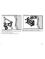
2. Drill 4 holes at the marked location on the template.
10
8.
2
m
m
(
4.
26
in
)
18
8.
0
m
m
(
7.
40
in
)
34
.6
m
m
(
1.
36
in
)
276.8
mm
(10
.90 in
)
299.4
mm
(11
.78 in
)
Pilot
hole
cen
ter
(4 p
ositio
ns)
CS
22 T
e m
p la
te
UP
I
MP
ORT
AN
T: Th
is d
ocu
men
t m
ay n
ot p
rint
true
to s
cale
. Be
fore
m
odif
ying
m
oun
ting
sur
face
,
ens
ure
prin
ted
tem
plat
e m
atch
es th
e m
easu
rem
ents
pro
vide
d.
Doc
um
ent n
um
ber:
871
42-1
Date
: 07
-201
1
R
aym
arin
e C
S22
dig
ital
sou
nde
r m
odu
le m
oun
ting
tem
pla
te
D
121
97-1
D12241-1
3. Remove the mounting template.
4. Screw in the supplied fixing screws about half way into the holes.
5. Place the unit onto the fixing screws.
6. Push the unit down to engage the key slots in the unit.
7. Tighten the screws
1
2
3
D12242-1
Note:
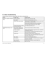
Drill bit, tap size and tightening torque is dependent on the
thickness and type of material the unit is to be mounted on.
32
CP450C
Summary of Contents for CP450C
Page 2: ......
Page 4: ......
Page 6: ...6 CP450C...
Page 18: ...18 CP450C...
Page 44: ...44 CP450C...
Page 52: ...52 CP450C...
Page 53: ...Owner notes...
Page 54: ...Owner notes...
Page 55: ......
Page 56: ...www raymarine com...


